TESTIMONIALS

What Our Clients Say?

About US

Industrial Automation Parts

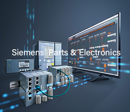
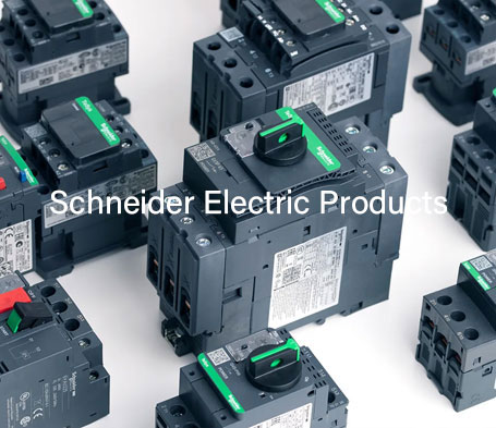
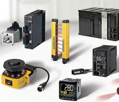
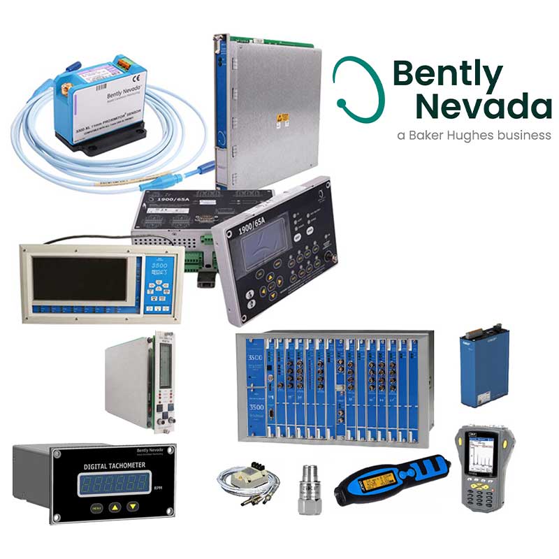
Xiamen Wusu Network Technology Co. Ltd. provides our clients with the industrial electronics parts they need right when they need them. We specialize in mature, legacy, and end-of-life products that you won't find anywhere else, and we keep failure-prone parts in stock to reduce lead times. We’ll stop at nothing to get you the industrial automation spare parts you need at a great price. Contact our team today if you have any questions.

Read More
video

Manufacturers

Hot Products

Huge Inventory Selection!

Dont't Hesitate To Contact Us Any Time

Read More

Blog Center

August 26,2026
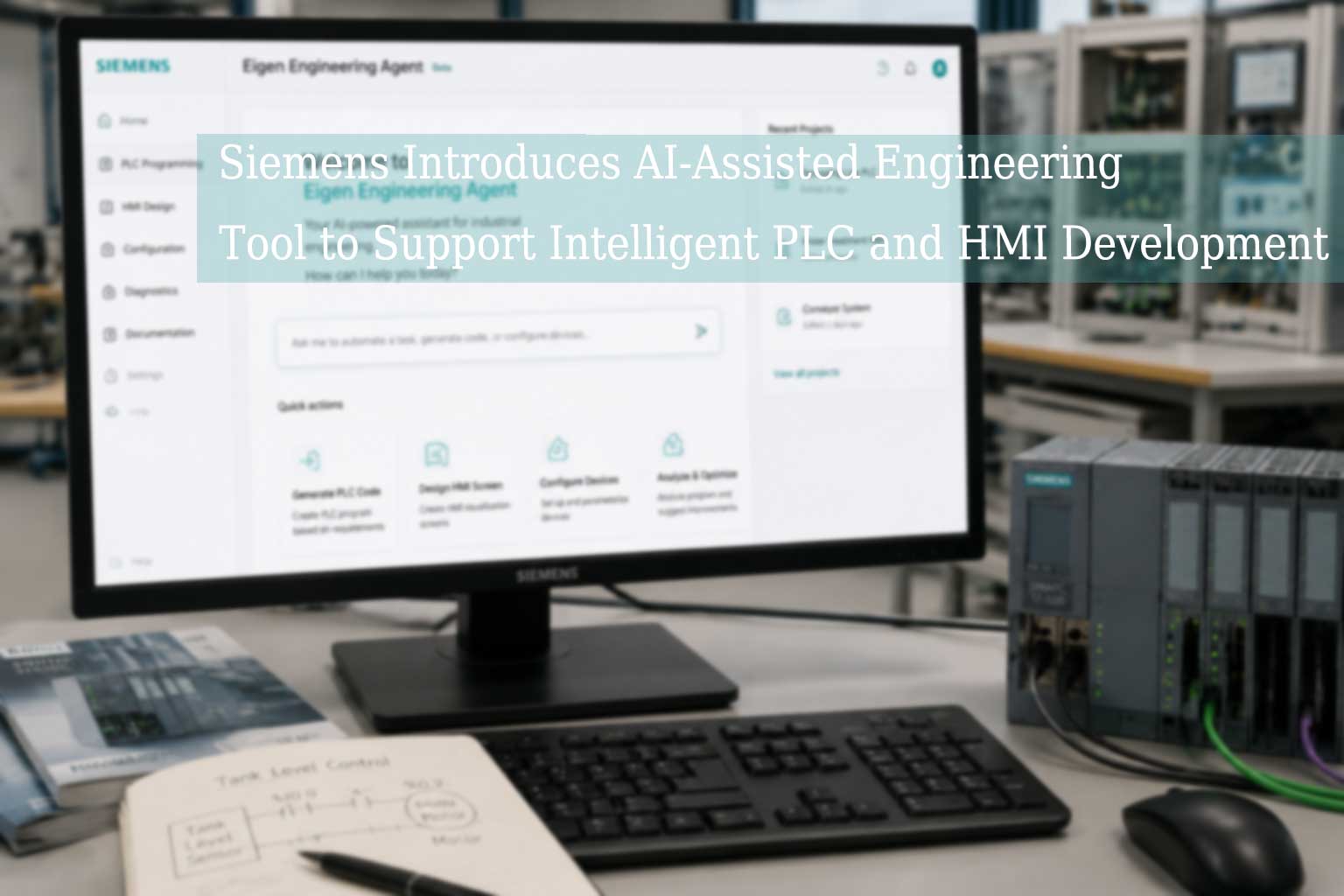
Siemens Introduces AI-Assisted Engineering Tool to Support Intelligent PLC and HMI Development

Siemens recently launched "Eigen Engineering Agent," an AI tool designed for automation engineering that assists with tasks such as PLC programming, HMI visualization, and equipment configuration.   By integrating AI technology, the tool provides development support to automation engineers, helping to optimize engineering design workflows and enhance flexibility during the implementation of automation projects.   As smart manufacturing and industrial digital transformation continue to advance, manufacturing enterprises are demanding higher standards for automation system development efficiency, equipment connectivity, and engineering maintenance capabilities.   Traditional industrial automation projects typically involve multiple stages, including: PLC program development HMI interface design Control system configuration Equipment parameter settings Industrial network connectivity   As production equipment becomes increasingly complex, automation engineering teams require more efficient tools to meet growing project demands.   Technology Impact AI technology is increasingly being applied to industrial automation engineering workflows.   AI-assisted tools provide support in the following areas: PLC engineering development assistance HMI screen design optimization Automation equipment configuration management Engineering information organization System development process support   The goal of this technology is not to replace automation engineers, but rather to use intelligent tools to handle repetitive tasks, thereby boosting project development efficiency.   Industry Significance For manufacturing enterprises, automation systems have evolved from simple equipment controls into comprehensive architectures integrating PLCs, HMIs, industrial networks, drive systems, and data management platforms.   The integration of AI and automation engineering will further drive: Smart factory construction Automation system upgrades Industrial data utilization Equipment maintenance optimization   In the future, automation equipment suppliers and engineering service providers will need to place greater emphasis on the convergence of software, hardware, and intelligent technologies.

Read More
August 26,2026
How to Choose the Right PLC for Industrial Automation Applications? Key Selection Factors and Application Guide

In modern manufacturing, the PLC (Programmable Logic Controller) remains a vital control core within industrial automation systems. From controlling production line equipment to managing robots, conveyor systems, and process control applications, PLCs are responsible for acquiring field signals, executing control logic, and exchanging data with HMIs, variable frequency drives (VFDs), and other industrial equipment.   With the advancement of smart manufacturing, enterprise requirements for PLC systems have evolved beyond basic control functions; there is now a greater focus on processing power, communication compatibility, scalability, and long-term maintenance needs. Consequently, selecting a PLC requires a comprehensive evaluation based on specific application scenarios and system requirements.   The Role of PLCs in Industrial Automation Systems PLCs are primarily used for automation control in industrial settings. They acquire signals from sensors, buttons, and equipment status via input modules, and then control the operation of output devices based on pre-programmed logic.   Modern PLC systems typically require connectivity with: Industrial HMIs (Human-Machine Interfaces) Variable frequency drives (VFDs) and servo drives Remote I/O modules Industrial robot systems Factory data management platforms   The Allen-Bradley ControlLogix series is typically used for large-scale automation systems, whereas the CompactLogix series is suited for small-to-medium-sized equipment and production line control needs. Different product series offer distinct characteristics regarding CPU performance, I/O expansion capabilities, and communication interfaces.   1. What key factors should be considered when selecting a PLC? Selecting the PLC performance level based on control requirements PLC performance must align with the complexity of the equipment control.   Small-scale machinery typically focuses on: Basic logic control A limited number of I/O points Simple communication requirements   In contrast, large-scale automated production systems require: Higher processing power Larger program capacity Capabilities for coordinated control across multiple devices   Therefore, the selection process requires evaluating the number of devices, control tasks, and future expansion needs.   2. Determining PLC configuration based on I/O count I/O configuration is a critical factor in PLC selection.   Enterprises need to determine: The number of digital inputs The number of digital outputs Analog input requirements Analog output requirements   If there are plans for future equipment expansion, space for additional modules should be reserved. For instance, modular PLC systems can typically meet production line upgrade needs through the addition of expansion modules.   3. Communication protocols affect system compatibility Modern industrial environments increasingly rely on data exchange between devices; therefore, PLC communication capabilities are crucial. Common industrial communication protocols include: EtherNet/IP PROFINET Modbus TCP EtherCAT   PLCs must establish stable connections with HMIs, industrial drives, and other control devices. For instance, when using an industrial variable frequency drive (VFD) to control motor speed, the PLC needs to read operating status and send control commands via the appropriate communication protocol.   4. Industrial environments determine PLC application reliability Different production environments impose varying requirements on PLC hardware.   Key considerations during selection include: Operating temperature range Installation environment Electrical interference levels Ingress protection (IP) rating requirements   For example, some industrial sites require equipment to operate continuously for long periods; consequently, the PLC module's design standards, installation method, and environmental adaptability directly impact the system's maintenance cycle.   How to select a PLC for different industry applications? Manufacturing production lines   The manufacturing industry typically requires PLCs to handle coordinated control across multiple devices, including sensor detection, motor control, and production process management.   Common requirements: Multi-device communication Rapid response System scalability Packaging machinery   Packaging equipment typically prioritizes: High-speed control Precise motion coordination Integration with servo systems   PLCs require robust motion control support and communication capabilities.   Process industries   Process industries typically require: Long-term operation Stable data acquisition Continuous process control   Therefore, greater emphasis is placed on system reliability and ease of maintenance.

Read More
July 24,2026
Industrial Automation Trends 2026: How PLC Systems Become the Core Control Platform for Smart Manufacturing

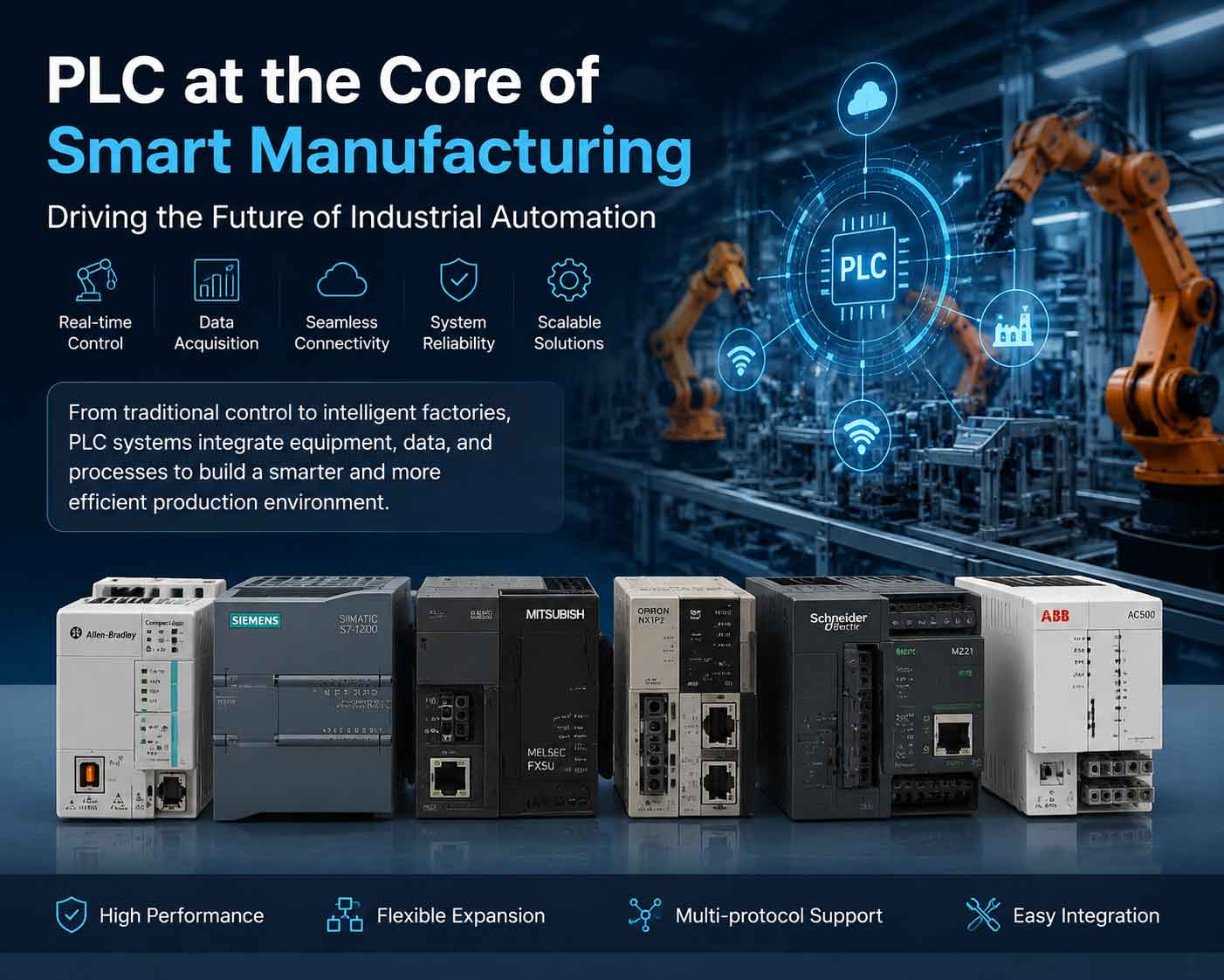
2026 Industrial Automation Trends: How PLCs Are Becoming the Core of Data Control in Smart Factories Smart Manufacturing Drives the Upgrade of PLC Control Systems   As the manufacturing sector advances toward digitalization and intelligence, traditional PLC control systems are evolving from simple logic control devices into vital nodes that connect equipment, data, and production management systems. In the past, PLCs were primarily responsible for equipment start/stop operations, sequence control, and field signal processing. Today, however, smart factories require PLCs to simultaneously handle real-time control, equipment communication, data acquisition, and system integration tasks. The industrial automation industry is accelerating the integration of AI, edge computing, and Industrial IoT technologies, driving the evolution of PLCs from traditional controllers into intelligent control platforms.    What industrial pain points do traditional PLC systems face? Inability to utilize equipment data in real time ,Many factories still operate PLC systems deployed years ago. While these systems are generally capable of basic automation control, they struggle to meet modern production demands, leading to issues such as: Difficulty in collecting equipment data Inability to monitor production status in real time Reliance on manual experience for fault analysis   Consequently, an increasing number of manufacturing enterprises are considering PLC upgrade solutions—such as adding communication modules or industrial gateways, or replacing existing units with next-generation PLCs—to enhance system data processing capabilities.   Shifting from breakdown repair to predictive maintenance for equipment Industrial equipment maintenance historically relied on: Scheduled inspections Post-failure repairs   Modern automation systems, however, focus more on: Monitoring equipment operating status Analyzing anomaly data Detecting potential issues in advance   Acting as the on-site control center, the PLC can collect: Temperature data Motor operating status Sensor signals Equipment alarm information   Integration with industrial software platforms enables smarter maintenance management.   Summary: PLCs Remain the Core Foundation of Industrial Automation Although industrial automation is rapidly integrating AI, cloud computing, and edge technologies, the PLC remains the most critical control foundation on the manufacturing floor. For enterprises upgrading equipment or building smart factories, selecting the right PLC control solution requires a comprehensive assessment of: Product compatibility Communication capabilities Scalability Long-term maintenance requirements   From traditional automation to smart manufacturing, the PLC remains a vital bridge connecting equipment with digital production.

Read More
December 03,2024
Basic logic instructions of Mitsubishi FX series PLC

Set and reset instructions (SET/RST)   (1) SET (set instruction) Its function is to set and maintain the target element being operated.   (2) RST (reset instruction) resets the target element being operated and keeps it in the cleared state. When the SET and RST instructions are used, when X0 is normally open and connected, Y0 becomes ON and remains in this state. Even if X0 is disconnected, Y0's ON state remains unchanged. Only when X1 is normally open and closed, Y0 becomes OFF and remains in this state. Even if X1 is normally open and disconnected, Y0 remains OFF.   Instructions for using SET and RST instructions:   1) The target elements of the SET instruction are Y, M, S, and the target elements of the RST instruction are Y, M, S, T, C, D, V, and Z. The RST instruction is often used to clear the contents of D, Z, and V, and is also used to reset the cumulative timer and counter.   2) For the same target element, SET and RST can be used multiple times in any order, but the last one executed is valid.   Master control instructions (MC/MCR)   1) MC (Master Control Instruction) is used for the connection of common series contacts. After executing MC, the left busbar moves behind the MC contact.   2) MCR (Master Control Reset Instruction) It is the reset instruction of the MC instruction, that is, the MCR instruction is used to restore the original position of the left bus.   In programming, it often happens that multiple coils are controlled by one or a group of contacts at the same time. If the same contacts are connected in series in the control circuit of each coil, a large number of storage units will be occupied. Using the main control command can solve this problem.   MC and MCR instructions use MC N0 M100 to move the left bus right, so that Y0 and Y1 are under the control of X0, where N0 represents the nesting level. In a non-nested structure, N0 can be used an unlimited number of times; MCR N0 is used to restore to the original left bus state. If X0 is disconnected, the instructions between MC and MCR will be skipped and executed downward.   Instructions for using MC and MCR instructions:   1) The target elements of MC and MCR instructions are Y and M, but special auxiliary relays cannot be used. MC occupies 3 program steps and MCR occupies 2 program steps;   2) The main control contact is perpendicular to the general contact in the ladder diagram. The main control contact is a normally open contact connected to the left busbar and is the main switch that controls a group of circuits. The contacts connected to the main control contact must use the LD or LDI instruction.   3) When the input contact of the MC instruction is disconnected, the cumulative timers, counters, and components driven by the reset/set instructions in MC and MCR maintain their previous states. Non-cumulative timers and counters, components driven by the OUT instruction will be reset. When X0 is disconnected in 22, Y0 and Y1 will become OFF.   4) Using MC instructions again in an MC instruction area is called nesting. The maximum number of nesting levels is 8, and the numbers increase in the order of N0→N1→N2→N3→N4→N5→N6→N7. The return of each level uses the corresponding MCR instruction, and resets from the nesting level with the largest number.   Differential instructions (PLS/PLF)   (1) PLS (rising edge differential instruction) generates a pulse output of one scan cycle on the rising edge of the input signal;   (2) PLF (falling edge differential instruction) generates a pulse output of one scan cycle at the falling edge of the input signal.   The edge of the signal is detected by the differential instruction, and the state of Y0 is controlled by the set and reset commands.   Instructions for using PLS and PLF instructions:   1) The target elements of PLS and PLF instructions are Y and M;   2) When using PLS, the target element is ON only within one scan cycle after the drive input is ON, and M0 is ON only within one scan cycle when the normally open contact of X0 changes from off to on; when using the PLF instruction, only the falling edge of the input signal is used for driving, and the rest is the same as PLS.

Read More
November 20,2024
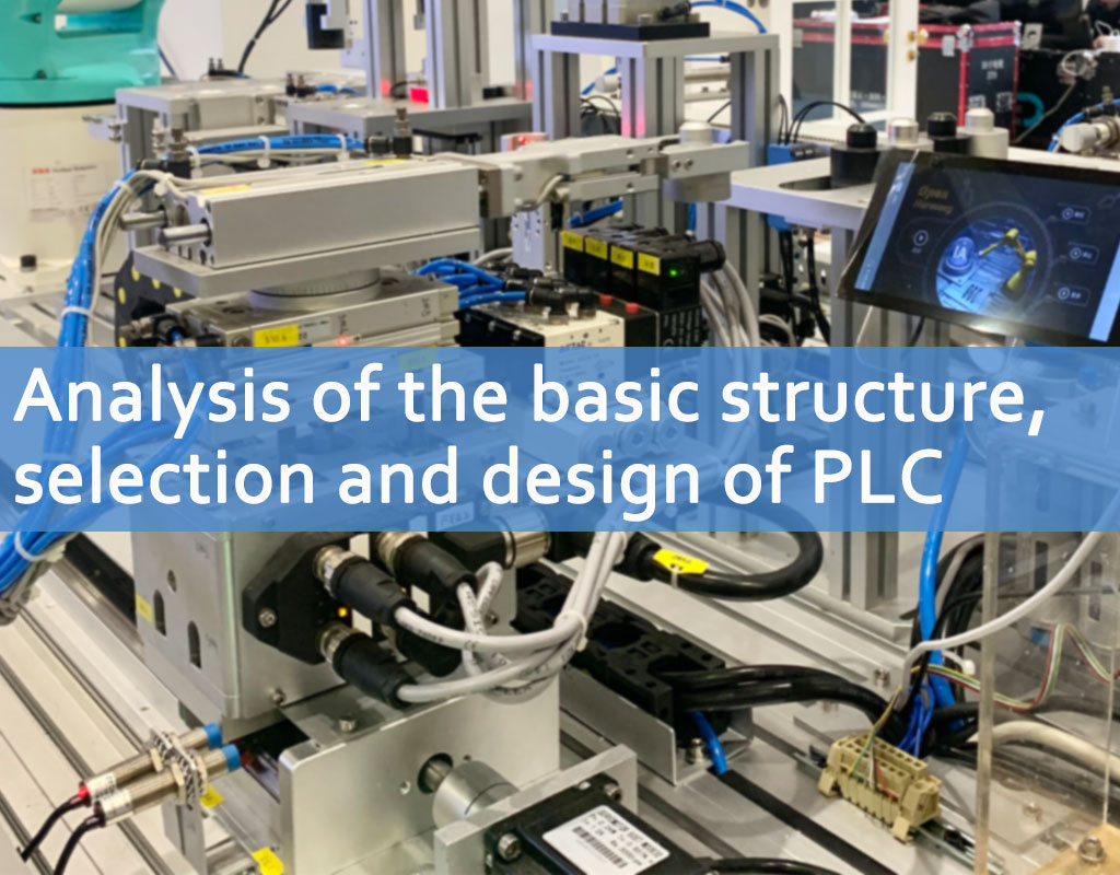
Analysis of the basic structure, selection and design of PLC

Basic structure   The essence of a programmable logic controller is a computer dedicated to industrial control. Its hardware structure is basically the same as that of a microcomputer. The basic structure is:   1. Power supply   The power supply of the programmable logic controller plays a very important role in the entire system. Without a good and reliable power supply system, it cannot work properly. Therefore, the manufacturer of the programmable logic controller also attaches great importance to the design and manufacture of the power supply. Generally, the AC voltage fluctuation is within the range of +10% (+15%), and the PLC can be directly connected to the AC power grid without taking other measures.   2. Central Processing Unit (CPU)   The central processing unit (CPU) is the control center of the programmable logic controller. It receives and stores the user program and data typed from the programmer according to the functions assigned by the programmable logic controller system program; checks the status of the power supply, memory, I/O and warning timer, and can diagnose syntax errors in the user program. When the programmable logic controller is put into operation, it first receives the status and data of each input device on site in a scanning manner, and stores them in the I/O image area respectively, and then reads the user program from the user program memory one by one, and after the command is interpreted, the results of the logical or arithmetic operation are sent to the I/O image area or data register according to the instructions. After all user programs are executed, the output status of the I/O image area or the data in the output register are finally transmitted to the corresponding output device, and the cycle runs until it stops.   In order to further improve the reliability of the PLC, large PLCs are also equipped with dual CPUs to form a redundant system, or a three-CPU voting system, so that even if a CPU fails, the entire system can still operate normally.   3. Memory   The memory that stores system software is called system program memory.   The memory that stores application software is called user program memory.   4. Input and output interface circuit   4.1. The field input interface circuit consists of an optical coupling circuit and a microcomputer input interface circuit, and serves as the input channel of the interface between the programmable logic controller and the field control.   4.2. The field output interface circuit is integrated with the output data register, the selection circuit and the interrupt request circuit, and the programmable logic controller outputs the corresponding control signal to the field execution component through the field output interface circuit.   5. Functional modules   Such as counting, positioning and other functional modules.   6. Communication module     PLC selection and case analysis   When selecting a PLC, you should analyze the characteristics of the process and the control requirements in detail, clarify the control tasks and scope, determine the required operations and actions, and then estimate the number of input and output points, required memory capacity, and determine the functions of the PLC and the characteristics of external devices based on the control requirements. Finally, select a PLC with a higher performance-price ratio and design a corresponding control system.   Below, we will detail the points that should be paid attention to when choosing PLC:   1. Estimation of Input and Output (I/O) Points Appropriate margin should be considered when estimating the number of I/O points. Usually, based on the statistical number of input and output points, an expandable margin of 10% to 20% is added as the estimated data for the number of input and output points.   2. Estimation of memory capacity; memory capacity is the size of the hardware storage unit that the programmable controller itself can provide, and program capacity is the size of the storage unit used by the user application project in the memory, so the program capacity is smaller than the memory capacity. In order to have a certain estimate of the program capacity during design and selection, the estimation of memory capacity is usually used as a substitute. Generally speaking, it is 10 to 15 times the number of digital I/O points, plus 100 times the number of analog I/O points, and this number is the total number of words in the memory (16 bits is one word), and another 25% of this number is considered as a margin. 3. Selection of control functions; this selection includes the selection of characteristics such as calculation function, control function, communication function, programming function, diagnostic function and processing speed.   (1) Operation function; the operation function of simple PLC includes logic operation, timing and counting function; the operation function of ordinary PLC also includes data shift, comparison and other operation functions; more complex operation functions include algebraic operation, data transmission, etc.; large PLC also has analog PID operation and other advanced operation functions. With the emergence of open systems, PLCs now have communication functions. Some products have communication with lower computers, some products have communication with the same computer or upper computer, and some products also have the function of data communication with the factory or enterprise network. When designing and selecting, we should start from the requirements of actual application and reasonably select the required operation functions. In most applications, only logical operation and timing and counting functions are needed. Some applications require data transmission and comparison. When used for analog detection and control, algebraic operation, numerical conversion and PID operation are used. Decoding and encoding operations are required to display data.   (2) Control functions: Control functions include PID control operations, feedforward compensation control operations, ratio control operations, etc., which should be determined according to control requirements. PLC is mainly used for sequential logic control. Therefore, single-loop or multi-loop controllers are often used in most cases to solve analog control. Sometimes, dedicated intelligent input and output units are also used to complete the required control functions, improve the processing speed of PLC and save memory capacity. For example, PID control units, high-speed counters, analog units with speed compensation, ASC code conversion units, etc. are used.   (3) Communication function: Large and medium-sized PLC systems should support a variety of fieldbuses and standard communication protocols (such as TCP/IP), and should be able to connect to the factory management network (TCP/IP) when necessary. The communication protocol should comply with ISO/IEEE communication standards and should be an open communication network. The communication interface of the PLC system should include serial and parallel communication interfaces (RS 232C/422A/485), RIO communication port, industrial Ethernet, common DCS interface, etc.; the main forms of the communication network of the PLC system are the following: 1) PC is the master station, and multiple PLCs of the same model are slave stations, forming a simple PLC network; 2) 1 PLC is the master station, and other PLCs of the same model are slave stations, forming a master-slave PLC network; 3) The PLC network is connected to a large DCS as a subnet of the DCS through a specific network interface; 4) Dedicated PLC network (dedicated PLC communication network of each manufacturer). In order to reduce the CPU communication task, according to the actual needs of the network composition, communication processors with different communication functions (such as point-to-point, fieldbus, industrial Ethernet) should be selected.   (4) Programming function; Offline programming mode: PLC and programmer share a CPU. When the programmer is in programming mode, the CPU only provides services for the programmer and does not control the field equipment. After programming is completed, the programmer switches to the running mode, and the CPU controls the field equipment and cannot be programmed. Offline programming can reduce system costs, but it is inconvenient to use and debug. Online programming mode: The CPU and programmer have their own CPUs. The host CPU is responsible for field control and exchanges data with the programmer within a scan cycle. The programmer sends the online compiled program or data to the host. In the next scan cycle, the host runs according to the newly received program. This method is more expensive, but the system debugging and operation are convenient, and it is often used in large and medium-sized PLCs.   (5) Diagnostic function The diagnostic function of PLC includes hardware and software diagnosis. Hardware diagnosis determines the fault location of hardware through hardware logic judgment, and software diagnosis is divided into internal diagnosis and external diagnosis. Diagnosis of the internal performance and function of PLC through software is internal diagnosis, and diagnosis of the information exchange function between PLC CPU and external input and output components through software is external diagnosis. The strength of the PLC's diagnostic function directly affects the technical capabilities required of operators and maintenance personnel, and affects the average repair time.   (6) Processing speed PLC works in scanning mode. From the perspective of real-time requirements, the processing speed should be as fast as possible. If the signal duration is less than the scanning time, the PLC will not be able to scan the signal, resulting in the loss of signal data. The processing speed is related to the length of the user program, the CPU processing speed, the software quality, etc. At present, the PLC contacts have fast response and high speed. The execution time of each binary instruction is about 0.2 to 0.4Ls, so it can adapt to the application needs with high control requirements and fast response requirements. The scanning cycle (processor scanning cycle) should meet the following requirements: the scanning time of small PLC is not more than 0.5ms/K; the scanning time of large and medium-sized PLC is not more than 0.2ms/K.   4. Model selection   (1) Types of PLC PLC is divided into two categories according to structure: integral type and modular type. It is divided into two categories according to application environment: field installation and control room installation. It is divided into 1 bit, 4 bit, 8 bit, 16 bit, 32 bit, 64 bit, etc. according to CPU word length. From the application point of view, it can usually be selected according to control function or input and output points. The I/O points of integral PLC are fixed, so users have less room for choice and are used in small control systems; modular PLC provides a variety of I/O cards or plug-in cards, so users can reasonably select and configure the I/O points of the control system. Function expansion is convenient and flexible, and it is generally used in large and medium-sized control systems.   (2) Selection of input and output modules; the selection of input and output modules should be consistent with application requirements. For example, for input modules, application requirements such as signal level, signal transmission distance, signal isolation, and signal power supply method should be considered. For output modules, the type of output module to be selected should be considered. Generally, relay output modules have the characteristics of low price, wide voltage range, short life, and long response time; thyristor output modules are suitable for frequent switching and inductive low power factor load occasions, but they are more expensive and have poor overload capacity. Output modules also have DC output, AC output, and analog output, which should be consistent with application requirements. According to application requirements, intelligent input and output modules can be reasonably selected to improve the control level and reduce application costs. Consider whether an expansion rack or remote I/O rack is needed.   (3) Power supply selection The power supply of PLC, in addition to the design and selection of PLC according to the requirements of the product manual when introducing equipment, the power supply of PLC should be designed and selected according to the requirements of the product manual. In general, the power supply of PLC should be designed and selected with 220VAC power supply, which is consistent with the voltage of the domestic power grid. For important applications, an uninterruptible power supply or a voltage-stabilized power supply should be used. If the PLC itself has a usable power supply, it should be checked whether the current provided meets the application requirements, otherwise an external power supply should be designed. In order to prevent the external high-voltage power supply from being introduced into the PLC due to misoperation, it is necessary to isolate the input and output signals, and sometimes a simple diode or fuse tube can be used for isolation.   (4) Memory selection: Due to the development of computer integrated chip technology, the price of memory has dropped. Therefore, in order to ensure the normal operation of the application project, the PLC memory capacity is generally required to be at least 8K memory according to 256 I/O points. When complex control functions are required, a larger capacity and higher grade memory should be selected.   (5) Economic Considerations When choosing a PLC, you should consider the performance-price ratio. When considering economic efficiency, you should also consider factors such as the scalability, operability, and input-output ratio of the application, make comparisons and take them into account, and finally select a more satisfactory product. The number of input and output points has a direct impact on the price. Each additional input and output card will increase the cost. When the number of points increases to a certain value, the corresponding memory capacity, rack, motherboard, etc. will also increase accordingly. Therefore, the increase in the number of points has an impact on the selection of CPU, memory capacity, control function range, etc. It should be fully considered during the estimation and selection to make the entire control system have a more reasonable performance-price ratio.  

Read More
August 20,2024
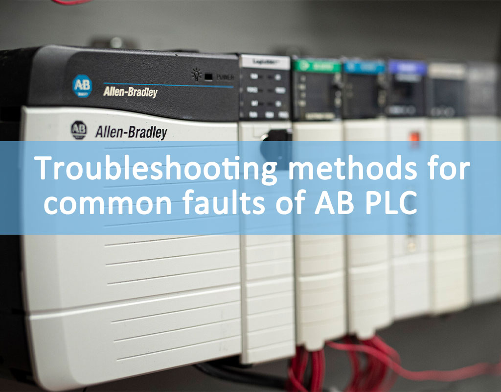
Troubleshooting methods for common faults of AB PLC

In the long-term maintenance of Rockwell AB's PLC controller, some knowledge about AB's PLC controller and some practical and effective troubleshooting methods for its common faults in actual production are summarized.   The hardware series of Rockwell AB's PLC include PLC5, ControlLogix, SLC500, MicroLogix, etc.; the commonly used communication software include RSLinx, etc.; the monitoring interface software include Intouch, RSView32, etc.; the programming software include RSLogix5, RSLogix500, RSLogix5000. Now we will give a brief introduction to the AB PLC controller used in our factory and the troubleshooting methods of common faults .   Controllogix   SLC 500 Series PLC (Medium-sized Control System) RSLinx software is a copy of RSLogix software. When performing CPU communication on RSLogix, you must first run RSLinx Lite, which is the interface software used for communication.   The module of SLC500 is generally 1746-×××, the CPU is 1747, and its addressing mode is the selection of slots. The power modules are generally 1746-P1, P2, P3, P4, of which only P3 is 24V DC and the rest are 220V AC input. The CPU of PLC5 is 1785-L20, L30..., which can connect up to four remote I/O channels and up to 32 remote I/O nodes (number of physical devices). The power module is 1771-P7. The addressing modes of PLC5 include 2-slot addressing, 1-slot addressing, and 1/2-slot addressing. 2-slot addressing means that each physical 2-slot I/O group corresponds to 1 word (16 bits) in the input/output image table. 1-slot addressing means that 1 physical slot corresponds to 1 word (16 bits) in the input/output image table. 1/2-slot addressing means that 1 physical slot corresponds to 2 words (32 bits) in the input/output image table.   Both types of CPUs have key switches that can be switched between RUN, PROG, and REM. RUN stands for operation, PROG stands for programming, and REM is between the two and can be defined by software as RUN or PROG. If it switches from RUN to REM, it is RUN, and if it switches from PROG to REM, it is PROG. The lights on the CPU of SLC500 include RUN, FLT, BATT, DH+, FORCE, and RS232. When they are on, they represent normal, fault, low battery, normal DH+ communication, forced output, and serial communication. When the light BATT on the CPU of PLC5 is on, it means that the battery voltage is low; PROC is green for operation and red for fault; FORC is on when it means that forced I/O is valid; CO is on when it is normal. The communication between them, including the remote adapter card, uses the DH+ communication link. The host computer communicates with the CPU by running the RSLinx Lite or RSLinx Gatewey software on the computer. Local programming can use RS-232 or DH+ communication links, and remote programming can use DH+ or Ethernet.   The programs in AB's PLC5 and SLC500 are generally not easily lost, so the faults are generally manifested as communication faults and module faults. The performance of AB's PLC hardware is relatively stable, so the dry ice line PLC has few faults. The common ones are generally the following:   1. The analog input quantity is displayed as a certain value and will not change. One situation occurs before starting up. In this case, first check whether the red light of the analog input module is on. If it is on, turn off the power and swap the modules to check whether the module is burned out. If it is broken, replace it. If it is not broken or the light is not on, it is a data transmission failure or a scanning failure. In this case, it can usually be restored by re-powering the PLC. The other situation occurs during operation. This situation is generally caused by a CPU module and analog module failure. Sometimes it can be restored by re-powering on. If it cannot be restored, it may be that the CPU module is broken.   2. The operation command is not executed, that is, the operation does not work. There are generally two possibilities for this situation. One is that the conditions that the operation should have are not met, so the operation does not work. The other is that the program is in its own closed loop, that is, an infinite loop or the scan time overflows, etc., causing output prohibition, or communication failure. In this case, you can stop the system first and then restart it, or turn off the power of the system and then turn it to automatic and start it to recover. If it cannot be recovered, re-powering the PLC can generally recover it.   3. All the outputs of the PLC are not working, that is, the indicator lights on the modules corresponding to the output points are not on. There are only one possible reason for this failure, that is, the 24V power supply provided by the output module is gone, one is that the intermediate relay that provides power to the output module is not in the condition of being attracted, and the other is that the coil of the intermediate relay is burned out or the contact is poor.   4. The signal is not received for a long time, causing a control unit to be unable to operate. This situation is a communication failure or data transmission failure, which can usually be restored by redoing the steps that generated the signal.   5. The green lights of all the input and output modules of the PLC are off. In this case, first check whether there is 220V AC at the input of the power module. If not, check the quality of the power supply transformer. If yes, the power module is broken.   6. During operation, the online device suddenly stops working, that is, the PLC suddenly "freezes". In this case, first check the status of the PLC. If the lights on all modules are off, it is very likely that the PLC power module is broken; if the lights on all modules are on when you press the CPU with your finger, then cut off the power, unplug the CPU and plug it in again. Generally, the fault can be eliminated. Another situation is that the input and output points of some input and output modules are not displayed. In this case, when eliminating the input and output module fault, unplugging and plugging the CPU can generally eliminate the fault.   7. If the DH+ or COM light on the CPU flashes or turns red, it means a communication fault. One case is that the DH+ cable is broken or the socket is loose. Check and fix the DH+ cable and socket until the fault disappears. Another case is that the communication address of the CPU is wrong or has been changed. In this case, you must enter RSLinx and click the communication configuration icon to reconfigure the address of the upper computer or PLC icon with a red cross until the red cross disappears.   8. The FLT fault light on the CPU flashes and the key cannot be reset. If the problem cannot be solved by checking the battery and modules, reconfigure the hardware download program.   In short, in the actual production process, we will encounter various PLC failures. Although the hardware performance of AB's PLC is relatively stable and the possibility of failure is very small, for us electrical maintenance personnel, whether it is AB's PLC or Siemens' PLC, as long as we use it, we must master it. Our knowledge of PLC programmable controller software and hardware is always lagging behind. Only by continuous learning and mastering some PLC maintenance methods and troubleshooting methods can PLC serve us better.  

Read More
August 19,2024
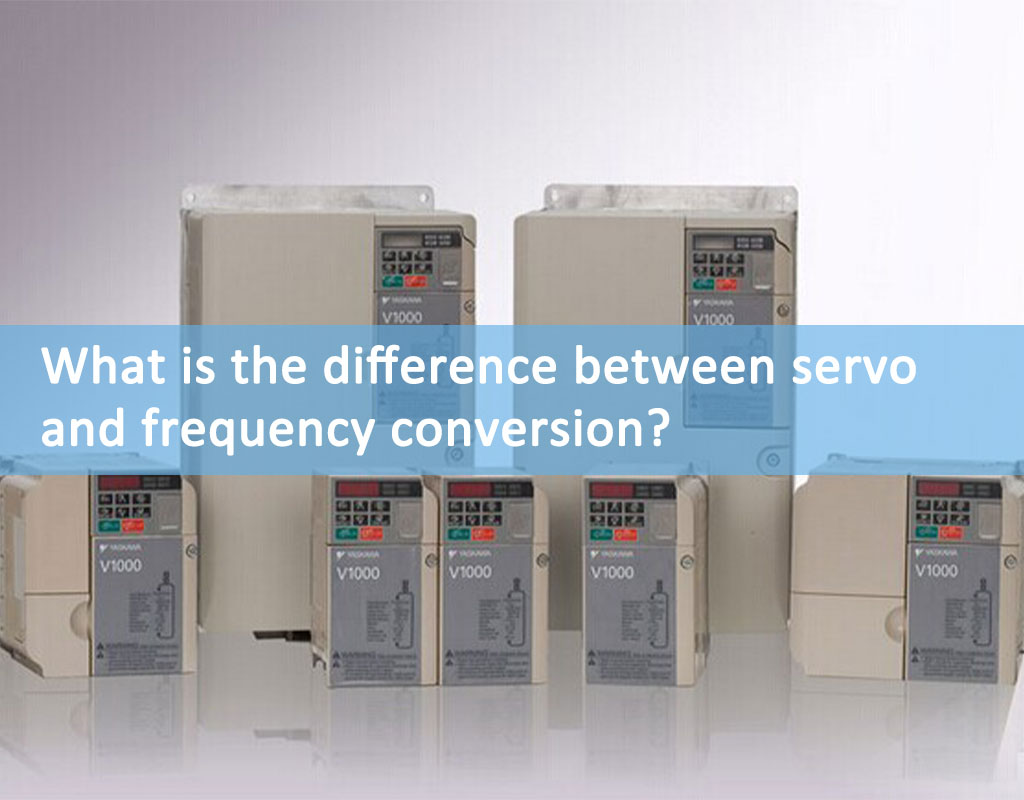
What is the difference between servo and frequency conversion?

What is a frequency converter   According to the definition of "GB/T 2900.1-2008 Basic Terms of Electrical Engineering": Frequency converter refers to an electric energy converter that changes the frequency related to electric energy.   Simple frequency converters can only adjust the speed of AC motors. It can be open-loop or closed-loop depending on the control method and frequency converter. This is the traditional V/F control method. Now many frequency converters have established mathematical models to convert the stator magnetic field UVW3 phases of AC motors into two current components that can control the motor speed and torque. Now most famous brands of frequency converters that can perform torque control use this method to control torque. The output of each phase of UVW must be added with a molar effect current detection device. After sampling and feedback, the PID adjustment of the current loop with closed-loop negative feedback is formed; ABB's frequency converter has proposed a direct torque control technology that is different from this method. Please refer to relevant information for details. In this way, both the speed and torque of the motor can be controlled, and the speed control accuracy is better than v/f control. Encoder feedback can be added or not. When it is added, the control accuracy and response characteristics are much better.   What is a servo   Driver: Based on the development of frequency conversion technology, the servo driver has implemented more precise control technology and algorithmic operations in the current loop, speed loop and position loop (the frequency converter does not have this loop) inside the driver than in general frequency conversion. It is also much more powerful than traditional servos in terms of functions. The main point is that it can perform precise position control. The speed and position are controlled by the pulse sequence sent by the upper controller (of course, some servos have integrated control units or directly set parameters such as position and speed in the driver through bus communication). The internal algorithm of the driver, faster and more accurate calculations, and better-performing electronic devices make it superior to the frequency converter.   Motor: The material, structure and processing technology of servo motors are much better than those of AC motors driven by inverters (general AC motors or various types of variable frequency motors such as constant torque and constant power). That is to say, when the driver outputs a power supply with rapidly changing current, voltage and frequency, the servo motor can produce corresponding action changes according to the power supply changes. The response characteristics and overload resistance are much better than those of AC motors driven by inverters. The serious difference in motors is also the fundamental reason for the difference in performance between the two. That is to say, it is not that the inverter cannot output a power signal that changes so quickly, but that the motor itself cannot respond. Therefore, when the internal algorithm of the inverter is set, a corresponding overload setting is made to protect the motor. Of course, even if the inverter output capacity is not set, it is still limited. Some inverters with excellent performance can directly drive servo motors!   An important difference between servo and frequency conversion   Frequency conversion can be done without encoders, but servos must have encoders for electronic commutation. The technology of AC servo itself is based on and applies frequency conversion technology. It is achieved by imitating the control method of DC motors through frequency conversion PWM on the basis of DC motor servo control. In other words, AC servo motors must have frequency conversion: frequency conversion is to rectify the 50, 60HZ AC power into DC power first, and then invert it into a frequency-adjustable waveform similar to sine and cosine pulsating power through various transistors with controllable gates (IGBT, IGCT, etc.) through carrier frequency and PWM regulation. Since the frequency is adjustable, the speed of the AC motor can be adjusted (n=60f/2p, n speed, f frequency, p pole pair number).

Read More
August 16,2024
How to solve the electromagnetic interference problem of servo drive system?

1. Classification of harmonic interference problems in servo drive systems The harmonic interference problems faced by the servo drive system can be divided into three categories according to the interference source and the disturbed source, namely, external harmonic interference to the servo drive system, servo drive system harmonic interference to the internal components of the servo drive system, and servo drive system interference to the outside world:   ⑴ External harmonics interfere with the servo drive system External harmonics mainly include: harmonics in the power supply, harmonics in nature (harmonics caused by lightning, etc.). These harmonics can cause a series of problems such as false alarms, false operations, and refusal to operate of the servo drive in the servo drive system. In more serious cases, the rectifier module and electrolytic capacitor in the servo drive may overheat, burst, explode, and other problems. Therefore, this part of the harmonics must be taken seriously.   ⑵ The servo drive system interferes with the internal components of the servo drive system This is a common situation. For example, the harmonics generated by the servo drive in the servo drive system can enter the servo motor, causing the servo motor to overheat, make noise (screaming, abnormal sound, etc.), vibrate (or oscillate), have pits, pits and cracks on the bearings, frequently break down the servo motor insulation, and severely shorten the life of the servo motor. Of course, the harmonics in the servo drive system will not only affect the servo motor, but may also affect a series of problems such as communication and analog signals.   ⑶ Servo drive system harmonic interference to the outside world There are two situations in which the servo drive system interferes with the outside world. One is that the harmonic interference of the servo drive system interferes with the electrical equipment that uses the same power supply, such as low voltage, instruments, meters, sensors, etc.; the other is that the harmonics of the servo drive system will radiate outward, causing the surrounding equipment to not work properly, such as communications, monitoring, instruments, meters, sensors, etc.   2. Solutions for reference to harmonic interference in servo drive systems When it comes to the harmonic interference problem of the servo drive system, first of all, don't blindly rush to install any servo harmonic suppression devices. This will not only increase costs and space occupancy, but also increase failure points. Therefore, this is not the preferred solution .   ⑴ Grounding Do a good job of grounding the servo drive system. The grounding of the servo drive system must be independent and distinguished from the grounding of other equipment; the grounding wire must be short and thick, and the wire diameter of the grounding wire must be at least half of the main wire diameter or more. We recommend that the grounding wire and the main wire of the servo drive system use the same wire diameter;   ⑵ Shielding It is recommended to use shielded wires for the connection wires between the servo drive system and the servo motor, and cut the shielding layer in a circular manner to expose the metal mesh, and then use a U-shaped clip or the like to ground it. For weak-wires such as communication lines and signal lines of the servo drive system, shielded wires should be used as much as possible, and the shielding layer should be reliably grounded;   ⑶ Filtering The filter components available for servo drive systems include: servo input filter, servo input inductor, MLAD-GFC servo-specific passive harmonic filter, servo-specific active harmonic filter, Du/Dt inductor, sine wave inductor, etc.  

Read More

July 31,2024
The Integration of the 2024 Paris Olympics with Industrial Automation

The Integration of the 2024 Paris Olympics with Industrial Automation   In 2024, France's Paris will host the highly anticipated global sporting event—the Summer Olympics. This is not only a grand celebration of athletic competition but also a showcase of technology and innovation. In this edition of the Olympics, the application of industrial automation technologies will provide robust support for the smooth running of the events, enhance the audience experience, and optimize resource management.   The Importance of Industrial Automation in the Olympics Industrial automation technology plays a crucial role in organizing and managing large-scale events in modern times. Through automated systems, efficient management of various aspects such as venues, transportation, and security can be achieved. For instance, automated warehousing systems can assist event organizers in effectively managing materials, ensuring that necessary equipment and supplies reach different venues on time.   Specific Application Cases 1.Intelligent Traffic Management During the Paris Olympics, a significant influx of spectators, athletes, and staff is expected in the city. To meet this challenge, Paris will utilize intelligent traffic solutions provided by Siemens. These systems monitor and adjust traffic flow through real-time data analysis and predictive algorithms, ensuring smooth traffic during the events.   2.Automated Security Systems Safety is paramount at large-scale events. Companies like Yaskawa and Honeywell will provide advanced security automation systems for the Olympics. These systems combine video surveillance, facial recognition technology, and drone monitoring to continuously oversee safety conditions inside and outside the venues, quickly identifying and addressing potential security threats.   3.Smart Venue Management In the area of venue management, Schneider Electric will provide smart building management systems. These systems can monitor energy consumption, temperature, and air quality in real-time to ensure optimal conditions in the venues throughout the different events. Additionally, automated controls can effectively reduce energy consumption, aligning with sustainability goals.   4.Robot Services With the advancement of robotics technology, robots will offer a variety of services during the events. Boston Dynamics will showcase its advanced service robots, which will guide spectators, provide information, and transport items within the venues, thereby enhancing the audience experience.   Conclusion The 2024 Paris Olympics is not only a stage for athletes to showcase their talents but also a proving ground for the application of industrial automation technologies. By introducing advanced automation solutions, Paris will present a safe, efficient, and intelligent Olympic experience to global audiences. The application of these technologies not only enhances event organization efficiency but also offers new ideas and directions for managing future large-scale events. With continuous technological advancements, we can believe that future Olympic Games will be even more intelligent and automated.

Read More
July 26,2024
What is PLC? What are its functions, characteristics and advantages?

PLC, or programmable logic controller, is an electronic device widely used in the field of industrial control. As a high-performance control device, PLC can be used in many fields such as automated production control, process control, logistics control, and data processing.   1). Definition of PLC   PLC is an electronic device used for industrial control, which contains multiple functional components such as CPU, memory, input and output ports, communication interface, etc. It controls through programs to realize the automatic control of various industrial equipment and machines. PLC first appeared in the 1960s, and since then, PLC has played an irreplaceable role in the field of industrial automation.     2). Characteristics of PLC   1. Programmability: PLC contains a variety of functional components, which can control and adjust the control process by writing programs, and can adapt to complex industrial control processes and production needs.   2. Stability: PLC has the characteristics of high stability and strong reliability, and can operate stably for a long time in complex and harsh industrial environments.   3. Scalability: PLC can add expansion boards according to production needs, thereby realizing the functional expansion of industrial production lines.   4. Easy to maintain: The modular design of PLC makes it easy to maintain, and faulty modules can be replaced quickly.     3). Advantages of PLC   1. Stable and reliable: PLC adopts high-quality electronic components and modular design, and can operate stably and reliably in complex industrial environments.   2. Efficient automatic control: PLC can realize automatic control of the control process by writing programs, reduce manual intervention and improve production efficiency.   3. Easy to maintain: The modular design of PLC makes it easy to maintain, and faulty modules can be quickly replaced, reducing downtime and repair costs.   4. High flexibility: The programmability of PLC enables it to flexibly adapt to different production needs, enhancing its scope of application.     4). Application of PLC   PLC is widely used in many fields such as automated production control, process control, logistics control and data processing. The following are some typical application examples:   1. Automated production control: PLC can be used for fully automated control of production lines, such as automatic assembly, automated sorting, and automated packaging.   For example, in a company's production line, it is necessary to automatically control the speed and position of goods on the conveyor belt to achieve fast and efficient logistics operations. The company installed a PLC control system and realized precise control of the speed, position and other parameters of the conveyor belt by writing programs, which greatly improved the efficiency and accuracy of logistics operations.     2. Process control: PLC can be used for automated control of various industrial processes, including water treatment, chemical manufacturing, food processing and pharmaceuticals.   For example, a water treatment plant needs to precisely control the flow of water. The plant uses a PLC control system and writes programs to achieve real-time monitoring and automatic control of water flow, water quality and other parameters, thereby ensuring that the water quality and flow are within a reasonable range and improving the efficiency and quality of water treatment.   3. Logistics control: PLC can be used for the automated control of various logistics equipment, including logistics sorting, cargo transportation, and automated storage.   For example, the truck loading and unloading platform needs to accurately control the unloading speed and position of the items. The truck loading and unloading platform adopts PLC control system, which can realize accurate control of the goods by writing programs, greatly improving the unloading efficiency and safety of the goods.     In short, PLC is a high-performance control system with advantages such as high stability and strong reliability. PLC is widely used in automated production control, process control, logistics control and data processing. Through PLC automated control, production efficiency can be improved, manual intervention can be reduced, product quality can be improved, and enterprises can be helped to reduce costs and improve market competitiveness.  

Read More
Subscribe

Please read on, stay posted, subscribe, and we welcome you to tell us what you think.

submit

Copyright 2026 @ Xiamen Wusu Network Technology Co., Ltd. .All Rights Reserved.Sitemap | Blog | XML | Privacy Policy Network Supported

leave a message

leave a message
If you are interested in our products and want to know more details,please leave a message here,we will reply you as soon as we can.
submit

Home

Products

whatsApp

contact