
News
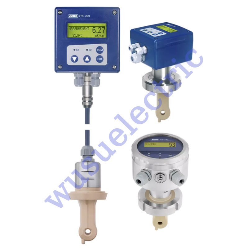
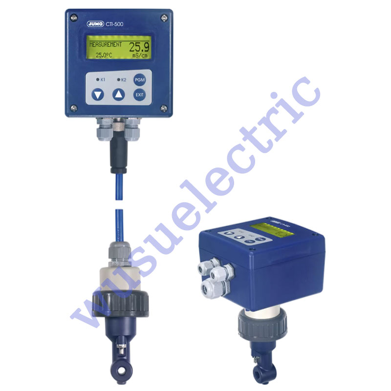
Temperature sensors are an indispensable component in modern industry, scientific research and daily life. Their stability and accuracy directly affect the operating efficiency and safety of the equipment. However, due to various factors, temperature sensors often encounter some faults during use. This article will analyze these common faults and propose corresponding treatment methods. Several common problems and solutions of wireless sensors: 1. After the wireless sensors are installed, the display jumps or the numbers are inaccurate in batches Cause: There is electromagnetic interference on site, or the signal line and power line run in the same cable tray. Solution: The performance of the product selected by the customer does not meet the on-site working conditions, and a transmitter with isolation function needs to be installed or replaced. 2. When the wireless sensor is installed, an error is displayed or no display is displayed Cause: The positive and negative wiring of the signal line is wrong Solution: Disconnect the power supply, swap the positions of the two signal lines, press them with the terminals, and then re-energize. This problem often occurs when installing PT100 thermal resistance sensors with three-wire output without a transmitter on site. 3. The displayed value of the wireless liquid level sensor remains unchanged after use Cause: Water in the airway Solution: Return the instrument to the factory for repair, drain the water from the air pipe, recalibrate the range, and then use it again. 4. The temperature sensor has no signal output Cause: When installing, the worker did not understand the sensor and used too much force, causing the pin of the temperature measuring element to be completely pulled out, breaking the signal circuit. Solution: When installing, just connect the wires to the terminals without removing the transmitter or magnetic plate, and use the terminals to press the signal leads. 5. The intelligent control instrument does not display when installed Reason: The instrument parameters are set incorrectly 6.Inaccurate sensor readings Cause: It may be due to sensor aging, dirt accumulation, environmental interference or improper calibration. Solution: Clean the sensor, check and recalibrate, and replace the sensor if necessary. 7.Slow sensor response time Cause: It may be due to the thermal inertia, material properties or improper installation position of the sensor. Solution: Select a sensor with faster response time, or optimize the installation position of the sensor. 8.The sensor output signal is unstable Cause: It may be due to electromagnetic interference, unstable power supply or internal fault of the sensor. Solution: Use shielded cables, ensure the power supply is stable, and check the internal circuit of the sensor. 9.Sensor damage Cause: It may be due to overload, shock or improper use. Solution: Replace the damaged sensor and ensure it is used within the specified working range. 10.Sensor connection issues Cause: It may be due to damaged cables, poor contact or corroded connectors. Solution: Check and repair the cables to ensure the reliability of the connection. 11.Sensor accuracy decreases Cause: It may be due to long-term exposure to extreme environment or sensor aging. Solution: Calibrate the sensor regularly or replace it with a new one. 12.Sensor overheating Cause: It may be due to high ambient temperature or poor heat dissipation of the sensor. Solution: Improve heat dissipation conditions or choose a high temperature resistant sensor. 13.The sensor is damp Cause: It may be due to high ambient humidity or poor sealing. Treatment method: Use moisture-proof measures such as sealant or moisture-proof agent.
view more
Siemens S7-200SMART PLC Issues Q: How can you convert a Siemens S7-200SMART PLC program into a S7-200 program?A: 1. In the S7-200 SMART software, right-click "Program Blocks" and select the export command to save the program as an *.awl file. In the S7-200 software, right-click "Program Blocks" and choose the import command to restore the *.awl file as a program. 2. You can also open both software programs simultaneously and transfer program segments using the clipboard. Q: How should you wire the RS485 communication for the Siemens S7-200SMART PLC with the expansion module signal board SB CM01?A: For RS485 wiring, connect positive to positive and negative to negative. On the SB COM1 signal board, Tx/B represents the 485 positive signal, and Rx/A represents the 485 negative signal. Q: What should you do if the Siemens S7-200SMART PLC compiles the program normally but shows a non-fatal error during download?A: Editing can only identify errors in the program that do not conform to programming principles. For non-fatal errors during download, check the recorded error information in the PLC menu under "Information" in the software. Q: Can the S7-200 PLC program be opened with the S7-200SMART PLC programming software?A: The S7-200 SMART programming software can directly open S7-200 programs, but the reverse is not possible; the S7-200 programming software cannot open S7-200 SMART programs. Q: The symbol table in STEP 7-MicroWIN SMART for Siemens S7-200SMART PLC cannot be opened. What might be the problem?A: Consider resetting the software interface. Go to the menu: View >> Components >> Reset View, then close and restart the software to initialize the interface. Q: Can the signal board of Siemens S7-200SMART PLC function as a master station when using the integrated 458 port for communication with a frequency converter and an extended 485 port for 1200RTU communication?A: Yes, the Siemens S7-200SMART PLC signal board can act as a master station. Q: The Siemens S7-200SMART PLC programming software won't start and shows a missing s7epaapi.dll error. How can this be fixed?A: Download the file from Baidu and place it in the system drive (C:). If you are using a 64-bit system, copy the 32-bit DLL file to C:\Windows\SysWOW64. Q: If the Siemens S7-200SMART PLC download fails with a message indicating that the port cannot be opened or is being used by another application, what should be done?A: Right-click on the computer, go to "Manage" >> "Services and Applications" >> "Services" and check if the "SIMATIC S7DOS Help Service" is running. If not, start the service. Q: The Siemens S7-200SMART PLC programming software displays "The specified file is an invalid project file" when opened. What might be the issue?A: This issue may occur if the current software version is lower than the version used to create the program. Lower versions of the software generally cannot open programs created with higher versions. Q: Is there any conflict between installing WinCC and Siemens S7-200SMART PLC programming software?A: There is no conflict; both can be installed without issues. Q: When switching PLC operation in Siemens S7-200 PLC programming software, a message says the PLC is in the wrong mode or the RUN/STOP switch is not in the TERM terminal position. What should be done?A: Ensure that the RUN/STOP switch is not in the STOP position. Set it to the TERM position to switch the PLC operation via software. Q: What does the "V memory not allocated to the library" error mean after compiling a Siemens S7-200SMART PLC program?A: Right-click on "Program Blocks," find the "Library Memory," and assign an address to it. Q: What is the purpose of SM0.1 in a Siemens S7-200SMART PLC program?A: SM0.1 is used for initialization tasks. It is activated only during the first scan cycle, meaning it will be on only during the initial scan and not in subsequent cycles. Q: What does it mean if the run, stop, and error lights on an S7-200 SMART ST20 PLC are all lit and yellow when powered on?A: If the lights are solid yellow, the CPU may be in a stopped state. If the error light is flashing yellow, it indicates a forced function in the program. Siemens S7-200 PLC Issues Q: How can you resolve the issue of "No access point found" when connecting a PPI programming cable to the 200CN PLC software PS9?A: Go to the Control Panel, find "PC/PG Interface Settings," and in the "Application Access Points" section, select "Add/Remove" and add a Microwin access point. Q: What should be done if Siemens software installation prompts to restart with "Please restart Windows before installing new programs"?A: This issue may be caused by leftover registry entries. Open the Windows menu, run "regedit," navigate to "HKEY_LOCAL_MACHINE\System\CurrentControlSet\Control\Session Manager," and delete the "PendingFileRenameOperations" entry without restarting the computer to proceed with the software installation. Q: What is the purpose of the transfer and comparison instructions in Siemens S7-200 PLC? How are they used?A: Comparison instructions compare the contents of two memory locations or data, resulting in true or false. Transfer instructions like MOV_B, MOV_W, and MOV_DW place values into specific addresses, depending on how the program is written and used. Siemens S7-300 PLC Issues Q: How can you install the Automation License Manager for Siemens S7-300 PLC?A: Install the Automation License Manager by running the setup.exe found in the STEP7 installation package under CD_1\Automation License Manager\Disk1. Q: Why does SIMATIC Manager in Siemens S7-300 programming software keep showing "No valid license key found"?A: This indicates that the software is not licensed. You need to acquire and apply the proper authorization. Q: What should be done if SIMATIC STEP7 V5.6 on Windows 10 shows "SIMATIC Manager registry database settings are incorrect. Please reinstall STEP 7"?A: Try running SIMATIC Manager as an administrator. If the issue persists, reinstall the software. Q: What does it mean if the SF indicator light is red on a Siemens S7-300 PLC?A: A red SF light indicates a system fault. Use the STEP7 hardware diagnostic function to perform a bus diagnosis and review diagnostic information to locate and resolve the issue. Q: How can you view the cross-reference table in Siemens S7-300 programming software?A: 1. Open the main interface of the 300 PLC programming software, go to the menu, and select "Options" and "Reference Data."2. Enter the new menu, find and select "Display and Jump."3. Confirm the corresponding view if no issues are found.4. After seeing the relevant results, you can view the cross-reference table. In STEP7, open "Blocks," then go to "Toolbar/Options/Reference Data" to view it. Other Siemens Issues Q: How can you resolve the issue of upgrading the firmware version of a WinCC flexible SMART V3 touchscreen if it gets stuck halfway?A: 1. Ensure the path does not contain Chinese characters.2. Check that the network cable or physical connections are secure.3. Confirm that ProSave is installed correctly and has not reported errors. Also, place the laptop in a stable location during OS updates to avoid vibrations that could pause hard disk operations. Q: Can PID be adjusted using a simulator for Siemens S7-1200 PLC?A: No, PID cannot be adjusted in simulation mode for Siemens S7-1200 PLC. Q: Can the TIA Portal V15 simulation software simulate Modbus TCP communication, or can it only simulate S7 communication?A: Both TCP/IP communication and S7 communication can be simulated. Q: Can the computer name in WINCC contain hyphens ("-")?A: 1. Computer names should start with letters and be composed of letter combinations.2. Avoid using spaces, backslashes, or underscores.3. If the name is functional, it is acceptable. Q: What is Siemens ET200SP?A: ET200SP is a distributed I/O station that supports PROFINET (PN) and PROFIBUS communication. Q: How many I/O modules can be expanded with ET200S?A: ET200S can be expanded with up to 64 I/O modules. Q: Can Siemens touchscreens upload screens?A: To upload screens, a CF card is required, and the upload function must be enabled during program download. Q: Can MMC cards be formatted using USB card formatters?A: No, MMC cards cannot be formatted using USB card formatters. Q: Are both ports on an industrial Ethernet interface used for PN communication?A: Yes, both physical ports on an industrial Ethernet interface support PROFINET communication. Q: How can I ensure that the PG/PC interface names in version 5.5 software match those in simulation interfaces?A: There is no need to change them; it is normal for the names to differ. Q: How do you change a normally open contact to a normally closed contact in STEP7?A: There is no direct key for this. Delete the normally open contact and then insert a normally closed contact.
view more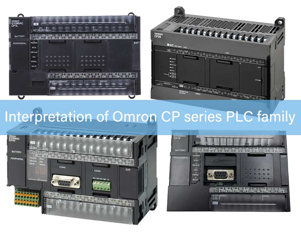
When using Omron's small CP series family PLC, many people cannot tell the difference between the various CPU models. Let's explain it below. Omron's CP series PLC is an integrated PLC with built-in pulse output, analog input and output, and serial communication functions. There are mainly 4 products: CP1 E, CP1L, CP1H, and CP2E. 1. CP1E is economical, easy to use, and efficient . It is the lowest cost product in the CP series. Although it is low-priced, it also has built-in high-speed counter function, pulse output function, and serial connection port. In addition, when using expansion units and option boards, it can support various device controls. The disadvantage is that it only supports two-axis pulse high-precision positioning control, and only supports transistor output type when two-axis pulse is used, and does not support FB function blocks and ST text writing. 2 .Features of CP1L Based on CP1E, it has an embedded Ethernet configuration and comes standard with Ethernet communication, which meets the requirements of instruments and equipment that use Ethernet communication. It supports FB function blocks and structured text ST programming. The disadvantage is that it only supports two-axis pulse high-precision positioning control and only supports transistor output type, and its cost price is higher than CP1E. 3. The characteristics of CP1H are that it is equipped with 4-axis pulse input and output and only supports transistor output type, supports Ethernet communication, supports FB function blocks and structured text ST programming. The disadvantage is that it does not have an Ethernet port as standard, and the cost price is higher than CP1E and CP1L. 4. The feature of CP2E is that it integrates functions that meet the needs of small-scale devices, integrates the performance of CP1E, CP1L, and CP1H, enhances connectivity with networks and peripheral devices, is equipped with 2 Ethernet ports, and does not require a switching hub. In addition to upper-level connection, the other end can also be used as a connection to HMI and PLC, a tool connection port, and a standby port, etc. It has a variety of usage methods, supports FB and ST text languages, and supports Ethacat bus. The disadvantage is that compared with other CP series, the cost price is high.
view more
1. The keyboard has no display after power-on 1.1 Check whether the input power supply is normal. If it is normal, measure the voltage at the P and N terminals of the DC bus to see if it is normal. If there is no voltage, turn off the power to check whether the charging resistor is damaged or short-circuited. 1.2 After checking, the voltage of P and N terminals is normal. You can replace the keyboard and keyboard cable. If there is still no display, you need to turn off the power and check whether the 26P cable connecting the main control board and the power board is loose or damaged. 1.3 If the switch power supply works normally after power-on, the relay has a closure sound, the fan runs normally, but there is still no display, it can be determined that the crystal oscillator or resonant capacitor of the keyboard is broken. At this time, the keyboard can be replaced or repaired. 1.4 If everything else is normal after power-on, but there is still no display, the switching power supply may not be working. At this time, you need to unplug the P and N power supplies after power off and check whether the static state of IC3845 is normal (check based on experience). If the static state of IC3845 is normal, the voltage across the 18V/1W voltage regulator diode is about 8V after adding DC voltage to P and N, but the switching power supply does not work. Turn off the power to check whether the rectifier diode on the secondary side of the switching transformer is short-circuited. 1.5 After power-on, the 18V/1W Zener diode has voltage, but there is still no display. You can remove some peripheral wires, including the relay wire plug and the fan wire plug, and check whether the fan or relay is short-circuited. 1.6 After the P and N terminals are powered on, the voltage across the 18V/1W Zener diode is about 8V. Use an oscilloscope to check whether there is a sawtooth wave at the input terminal ④ of IC3845 and whether there is output at the output terminal ⑥. 1.7 Check whether there is a short circuit between the output terminals +5V, ±15V, +24V of the switching power supply and each drive power supply to the ground and between the poles. 2. The keyboard displays normally but cannot be operated 2.1 If the keyboard display is normal, but the function keys cannot be operated, you should check whether the keyboard used matches the main control board (whether it contains IC75179). For machines with internal and external keyboard operations, you should check whether the DIP switch position you set is correct. 2.2 If the display is normal but some buttons cannot be operated, check whether the button micro switch is defective. 3. The potentiometer cannot adjust the speed 3.1 First check whether the control method is correct. 3.2 Check whether the given signal selection and analog input mode parameter settings are valid. 3.3 Check whether the DIP switch settings on the main control board are correct. 3.4 If all of the above are correct, the potentiometer may be defective and the resistance value should be checked to see if it is normal. 4. Overcurrent protection (OC) 4.1 When "FO OC" is displayed on the inverter keyboard and "OC" flashes, you can press the "∧" key to enter the fault query state, and you can find the operating frequency, output current, operating status, etc. at the time of the fault. According to the operating status and output current, you can determine whether the "OC" protection is overload protection or Vce protection (output short circuit, drive circuit failure and interference, etc.). 4.2 If it is determined during the query that the current is too large during acceleration due to heavy load, then adjust the acceleration time and the appropriate V/F characteristic curve appropriately. 4.3 If the inverter jumps to "OC" protection when the motor is not connected and the inverter is running idle, the power should be turned off to check whether the IGBT is damaged, and whether the junction capacitance between the IGBT's freewheeling diode and GE is normal. If normal, the drive circuit needs to be checked: ① Check whether the drive line is plugged in correctly, whether there is offset, and whether it is plugged in vain. ② Check whether the "OC" is caused by poor HALL and line. ③ Check whether the drive circuit amplifier element (such as IC33153, etc.) or the optical coupler is short-circuited. ④ Check whether the drive resistor is open-circuited, short-circuited, or has resistance value changes. 4.4 If “OC” jumps during operation, check whether the motor is blocked (mechanically stuck), causing a sudden change in load current and causing overcurrent. 4.5 If “OC” jumps during deceleration, the deceleration time and deceleration mode need to be adjusted accordingly according to the type and weight of the load. 5. Overload protection (OL) 5.1 When "FO OL" is displayed on the inverter keyboard and "OL" flashes, you can press the "∧" key to enter the fault query state, and you can check the operating frequency, output current, operating status, etc. at the time of the fault. According to the operating status and output current, if the output current is too large, it may be caused by excessive load. At this time, you should adjust the acceleration and deceleration time, V/F curve, torque boost, etc. If it is still overloaded, you should consider reducing the load or replacing the inverter with a larger capacity. 5.2 If the output current is not large when checking the fault, you should check whether the parameters of the electronic thermal overload relay are appropriate. 5.3 Check whether the HALL and wires are defective. 6. Overheat protection (OH) 6.1 Check whether the temperature switch wire is properly plugged in, and use a multimeter to check whether the temperature switch wire is disconnected. If it is disconnected, it can be concluded that the temperature switch wire is broken or the temperature switch is damaged. 6.2 Fan failure causes overheating protection. 6.3 The ambient temperature is too high, the heat dissipation effect is poor, and the internal temperature of the inverter is high, resulting in overheating protection. 6.4 For the inverter with seven-unit IGBT with rectifier bridge, the temperature detection is carried out by using the resistance change of the thermistor inside the IGBT. If the "OH" overheat protection appears, there are the following reasons: ① The comparator is broken and the output is high level. ② The comparison resistance of the comparator changes and the comparison voltage is low. ③ The resistance of the thermistor inside the IGBT is abnormal. 7. Overvoltage protection (OU) 7.1 The inverter has overvoltage protection during deceleration due to large load inertia. At this time, the deceleration time should be extended. If it is still ineffective, a braking unit and a braking resistor can be installed to consume energy. 7.2 Due to the overvoltage protection caused by replacing the power board or main control board, the VpN parameter resistor needs to be adjusted. 7.3 If the input power voltage is much higher than the rated voltage of the inverter, overvoltage may also occur. 8. Undervoltage protection (LU) 8.1 First check whether the input power voltage is normal, whether the wiring is in good condition, and whether there is any phase loss. 8.2 Is the “04” value parameter resistor appropriate? 8.3 Due to the replacement of the power board or the main control board, the undervoltage protection caused by the replacement of the power board or the main control board requires adjustment of the VpN parameter resistor. 8.4 Voltage detection circuit, operational amplifier and other device defects can also cause undervoltage. 9. There is frequency display, but no voltage output 9.1 After the inverter is running, there is a running frequency, but there is no voltage output between U, V, and W. At this time, it is necessary to check whether the carrier frequency parameters are lost. 9.2 If the carrier frequency parameters are normal, you can run the inverter and use an oscilloscope to check whether its drive waveform is normal. 9.3 If the driving waveform is abnormal, you need to check whether the SPWM waveform sent by the main control board CPU is normal. If it is abnormal, the CPU is faulty. If the SPWM waveform of the main control board is normal, you need to cut off the power and replace the 26P cable and try again. If the driving waveform of the driver board is still abnormal, the driving circuit part is faulty and needs to be repaired or replaced. 10. The relay does not close 10.1 First, check whether the input power is abnormal (such as lack of phase). 10.2 Check whether the connection between the power board and the capacitor board is correct and whether there is any looseness. 10.3 Check whether the 26P cable between the main control board and the power board has poor contact or is broken, which causes the REC control signal to be invalid and the relay to fail to energize. 10.4 Damage to components in the relay's energizing circuit may also cause the relay to fail to energize. 10.5 The relay is damaged internally (such as coil breakage, etc.).
view more
1. Under what environment can Siemens Step7Micro/WINV4.0 be installed to work properly? The installation and operation environment of Step7Micro/WINV4.0 is: WINOOWS2000SP3 or later WINOOWsXPHome WINOOWsXPProfessional Siemens PLC has not been tested under other operating systems and is not guaranteed to work. 2. What is the compatibility between Step7Micro/WINV4.0 and other versions? Project files generated by Micro/WINV4.0 cannot be opened or uploaded by older versions of Micro/WIN. 3. What are the differences between Siemens 200 PLC hardware versions? The second-generation S7-200 (CPU22x) series is also divided into several major hardware versions. 6ES721x-xxx21-xxxx is version 21; 6ES721x-xxx22-xxxx is version 22. Compared with version 21, version 22 has improved hardware and software. Version 22 is backward compatible with the functions of version 21. The main differences between version 22 and 21 are: http://www. plcs.cn The free port communication rates 300 and 600 of the 21st version CPU are replaced by 57600 and 115200 of the 22nd version. Version 22 no longer supports 300 and 600 baud rates, and version 22 no longer has restrictions on the location of the smart module 4. How to connect the power supply of Siemens PLC? When wiring the CPU, you must be especially careful to distinguish which power supply method it is. If you connect 220VAC to a 24VDC powered CPU, or accidentally connect it to a 24VDC sensor output power supply, the CPU will be damaged. 5: How many bits does the S7-200PLC processor have? The data length of the central processing chip of S7-200CPU is 32 bits. This can also be seen from the data length of CPU accumulator AC0/AC1/AC2/AC3. 6. How to calculate the power supply requirements of S7-200? The S7-200CPU module provides 5VDC and 24VDC power supplies: When there is an expansion module, the CPU provides it with 5V power through the I/O bus. The sum of the 5V power consumption of all expansion modules cannot exceed the power rating provided by the CPU. If it is not enough, an external 5V power supply cannot be connected. Each CPU has a 24VDC sensor power supply, which provides 24VDC for the local input points and expansion module input points and expansion module relay coils. If the power requirement exceeds the power rating of the CPU module, you can add an external 24VDC power supply to provide it to the expansion module. The so-called power calculation is to use the power capacity that the CPU can provide, minus the power consumption required by each module. Notice: The M277 module itself does not require a 24VDC power supply, which is dedicated to the communication port. The 24VDC power supply requirement depends on the load on the communication port. The communication port on the CPU can connect the PC/PPI cable and TD200 and power them, and this power consumption does not need to be included in the calculation. 7. Can 200PLC work at minus 20 degrees? The working environment requirements of S7-200 are: 0°C-55°C, horizontal installation 0°C-45°C, vertical installation Relative humidity 95%, non-condensing Siemens also provides S7-200 wide temperature range products (SIPLUSS7-200): Operating temperature range: -25°C to +70°C Relative humidity: 98% at 55°C, 45% at 70°C Other parameters are the same as those of ordinary S7-200 products Each wide temperature range product of S7-200 has its own order number, which can be found on the SIPLUS product homepage. If you cannot find it, it means that there is no corresponding SIPLUS product at present. There are no wide temperature models for text and graphic display panels. Please also note that there is no stock in China. If you need it, please contact your local Siemens office or dealer. 8. How fast does the digital input/output (DI/DO) respond? Can it be used for high-speed input and output? S7-200 has hardware circuits (chips, etc.) on the CPU unit to process high-speed digital I/O, such as high-speed counters (inputs) and high-speed pulse outputs. These hardware circuits work under the control of user programs and can reach very high frequencies; but the number of points is limited by hardware resources. The S7-200 CPU works cyclically according to the following mechanism: Read the status of the input point to the input image area Execute the user program, perform logical operations, and obtain the new state of the output signal Write the output signal to the output image area As long as the CPU is in operation, the above steps are repeated. In the second step, the CPU also performs communication, self-checking and other tasks. The above three steps are the software processing of S7-200CPU, which can be regarded as the program scanning time. In fact, the processing speed of digital quantity by S7-200 is limited by the following factors: Input hardware delay (the time from the moment the input signal changes state to the moment the CPU can recognize the change when refreshing the input image area) The internal processing time of the CPU includes: Read the status of the input point to the input image area Execute the user program, perform logical operations, and obtain the new state of the output signal Write the output signal to the output image area Output hardware delay (the time from when the output buffer status changes to when the actual level of the output point changes) The above three time periods A, B, and C are the main factors that limit the response speed of Siemens PLC in processing digital quantities. An actual system may also need to consider the delay of input and output devices, such as the action time of the intermediate relay connected to the output point. The above data are all marked in the "S7-200 System Manual", and here is just a list comparison. The delay (filter) time of some input points on the CPU can be set in the "System Block" of the programming software Micro/WIN, and the default filter time is 6.4ms. If a signal that is susceptible to interference is connected to a DI point on the CPU that can change the filter time, adjusting the filter time may improve the quality of signal detection. The input points that support high-speed counter function are not subject to this filter time constraint when the corresponding function is enabled. The filter setting is also effective for the refresh of input image area, switch input interruption, and pulse capture function. Some output points are faster than others because they can be used for high-speed output functions and have special hardware designs. When the hardware high-speed output function is not used, they are just processed like ordinary points. The relay output switching frequency is 1Hz. 9. What are the countermeasures for S7-200 to handle fast response signals? Use the CPU's built-in high-speed counter and high-speed pulse generator to process the sequence pulse signal; Use the hardware interrupt function of some CPU digital input points and process them in the interrupt service program; the delay of entering the interrupt can be ignored; The S7-200 has "direct read input" and "direct write output" instructions that can bypass the time limit of the program scan cycle; Use the "pulse capture" function of some CPU digital input points to capture short pulses; Note: The minimum period of a scheduled task in the S7-200 system is 1ms. All measures to achieve fast signal processing must take into account the impact of all limiting factors. For example, it is obviously unreasonable to choose hardware with a 500μs output delay for a signal that requires a millisecond response speed. 10. Is there any relationship between S7-200 program scan time and program size? Program scan time is proportional to the size of the user program. The S7-200 System Manual contains data on the execution time required for each instruction. In practice, it is difficult to accurately calculate the program scan time in advance, especially before starting to program. It can be seen that the conventional PLC processing mode is not suitable for digital signals with high time response requirements. It may be necessary to adopt some special methods according to the specific task. 11. What is the fastest speed that CPU224XP high-speed pulse output can reach? The high-speed pulse outputs Q0.0 and Q0.1 of CPU224XP support frequencies up to 100KHz. Q0.0 and Q0.1 support 5-24VDC output. http://www.plcs.cn But they must be grouped with Q0.2-Q0.4 to output the same voltage. High-speed output can only be used in CPU224XPDC/DC/DC model . 12. Does the analog input on the CPU224XP body also respond at high speed? Its response speed is 250ms, which is different from the data of the analog expansion module. The analog I/O chip on the CPU224XP body is different from that used in the analog module, and the conversion principle used is different, so the accuracy and speed are different. 13: How to assign the address of the analog module behind CPU224XP The analog I/O addresses of S7-200 always increase by 2 channels/modules. So the address of the first analog input channel after CPU224XP is AIW4; the address of the first output channel is AQW4, and AQW2 cannot be used. 14. What communication protocols does the communication port on the S7-200CPU support? 1) PPI protocol: a communication protocol developed by Siemens specifically for S7-200; 2) MPI protocol: not fully supported, can only be used as a slave 3) Free port mode: A user-defined communication protocol used to communicate with other serial communication devices (such as serial printers, etc.). The S7-200 programming software Micro/WIN provides communication functions implemented through the free port mode: 1) USS instruction library: for S7-200 and Siemens inverters (MM4 series, SINAMICS G110 and old MM3 series) 2) ModbusRTU instruction library: used to communicate with devices that support the ModbusRTU master protocol The two communication ports on the S7-200 CPU are basically the same, with no special differences. They can work in different modes and communication rates; their port addresses can even be the same. Devices connected to the two communication ports on the CPU do not belong to the same network. The S7-200 CPU cannot act as a bridge. 15. What can the communication port on the S7-200 CPU be used for? 1) A programming computer with the programming software Micro/WIN installed can program the PLC; 2) Can connect to the communication ports of other S7-200CPUs to form a network; 3) Can communicate with the MPI communication port of S7-300/400; 4) Can connect to Siemens HMI devices (such as TD200, TP170micro, TP170, TP270, etc.); 5) Data can be published through: OPC Server (PCAccess V1.0); 6) Can connect to other serial communication devices; 7) Can communicate with third-party HMI; 16. Can the communication port on the S7-200 CPU be expanded? It is not possible to expand a communication port with the same function as the CPU communication port. If there are not enough communication ports on the CPU, you can consider: 1) Purchase a CPU with more communication ports; 2) Check the types of connected devices. If there is a Siemens human-machine interface (HMI, operation panel), consider adding an EM277 module and connecting the panel to the EM277. 17. What is the actual communication distance of the communication port on the S7-200 CPU? The data given in the "S7-200 System Manual" is a network segment of 50m, which is the communication distance that can be guaranteed under the network conditions that meet the specifications. For any distance exceeding 50m, a repeater should be added. Adding a repeater can extend the communication network by 50 meters. If a pair of repeaters are added, and there is no S7-200CPU station between them (EM277 can be used), the distance between repeaters can reach 1000 meters. Meeting the above requirements can achieve very reliable communication. In fact, some users have achieved communication over a distance of more than 50m without adding repeaters. Siemens cannot guarantee that such communication will be successful. 18. What factors should users consider when designing a network? 1) The communication port on the S7-200 CPU is electrically an RS-485 port, and the distance supported by RS-485 is 1000m; 2) The communication port on the S7-200CPU is non-isolated, so you need to ensure that the potential of each communication port on the network is equal; 3) Signal transmission conditions (network hardware such as cables, connectors, and external electromagnetic environment) have a great impact on the success of communication; 19. Does S7-200 have a real-time clock? CPU221 and CPU222 do not have a built-in real-time clock and require an external "clock/battery card" to obtain this function. CPU224, CPU226 and CPU226XM all have a built-in real-time clock. 20. How to set the date and time values to start moving? 1) Use the menu command PLC> Time of Day Clock... in the programming software (Micro/WIN) to set it through online connection with the CPU. After completion, the clock starts to move; 2) Write a user program and use the Set_RTC (set clock) instruction to set it. 21. How are the addresses of smart modules assigned? In addition to the digital and analog I/O expansion modules occupying input/output addresses in the S7-200 system, some intelligent modules (special function modules) also need to occupy addresses in the address range. These data addresses are used by the modules for functional control and are generally not directly connected to external signals. In addition to using IB/QB as status and control bytes, CP243-2 (AS-Interface module) uses AI and AQ for address mapping of AS-Interface slaves. 22. What is the compatibility of Step7-Micro/WIN? The most common Micro/WIN versions are V4.0 and V3.2. Older versions, such as V2.1, are no longer valuable except for converting old project files. Different versions of Micro/WIN generate different project files. A higher version of Micro/WIN is backward compatible with project files generated by lower versions of software; lower versions of software cannot open higher versions. Saved project files. It is recommended that users always use the latest version, which is currently Step7-Micro/WIN V4.0 SP1. 23. How to set the communication port parameters? By default, the communication port of S7-200CPU is in PPI slave mode, the address is 2, and the communication rate is 9.6K. To change the address or communication rate of the communication port, you must set it in the CommunicaitonPorts tab in the system block, and then download the system block to the CPU for the new settings to take effect. 24. How to set the communication port parameters to improve the network performance? Assume that there are stations 2 and 10 as master stations in a network, and the highest address (of station 10) is set to 15. For station 2, the so-called address gap is the range from 3 to 9; for station 10, the address gap is the range from 11 to the highest station address 15, and also includes stations 0 and 1. The master stations in the network communication will pass tokens between each other to control the communication activities on the entire network in a time-sharing manner. All the master stations on the network will not join the token passing ring at the same time, so a master station holding a token must regularly check whether there are new master stations joining the station address higher than itself. The refresh factor refers to the number of times the higher station address is checked after obtaining the token. If the address gap factor 3 is set for station 2, when station 2 gets the token for the third time, it will check an address in the address gap to see if there is a new master station joining. Setting a larger factor will improve network performance (because there are fewer unnecessary site checks), but it will affect the speed at which new master sites are added. The following settings will improve network performance: 1) Set the highest address that is closest to the actual highest station address 2) Make all master station addresses arranged continuously so that new master station detection will not be performed in the address gap. 25. How to set the data hold function? Data retention settings define how the CPU handles the data retention tasks of each data area. The data area selected in the data retention setting area is the data area whose data content is to be "retained". The so-called "retention" means whether the content of the data area remains in the state before the power failure after the CPU is powered off and then powered on. The data retention function set here is implemented in the following ways: The data retention function set here is realized by the supercapacitor built into the CPU. After the supercapacitor is discharged, if an external battery (or clock/battery for CPU221/222) card is installed, the battery card will continue to supply power for data retention until the discharge is completed. The data will be automatically written into the corresponding EEPROM data area before power failure (if MB0-MB13 is set to retention). 26. What is the relationship between data retention settings and EEPROM? 1) If the storage units in the 14-byte range of MB0-MB13 are set to "keep", the CPU will automatically write their contents to the corresponding areas of the EEPROM when the power is off, and overwrite these storage areas with the contents of the EEPROM after power is restored; 2) If the range of other data areas is set to "not retained", the CPU will copy the values in the EEPROM to the corresponding addresses after power is turned on again; 3) If the data area range is set to "Retain", if the built-in super capacitor (+ battery card) fails to successfully retain the data, the contents of the EEPROM will overwrite the corresponding data area, otherwise it will not be overwritten. 27: What are the different types of passwords? Set the CPU password in the system block to restrict user access to the CPU. Passwords can be set in different levels to give other people different levels of authority. 28. After setting the CPU password, why can't I see that the password has taken effect? After setting the CPU password in the system block and downloading it, because you still maintain the communication connection between Micro/WIN and the CPU, the CPU will not protect the Micro/WIN with the password set. To verify that the password is valid, you can: 1) Stop the communication between Micro/WIN and CPU for more than one minute; 2) Close the Micro/WIN program and then reopen it; 3) Stop the power supply to the CPU and then supply power again; 29. Is there a freeze function for digital/analog quantities? The digital/analog output table specifies how the digital output points or analog output channels operate when the CPU is in the STOP state. This function is very important for some equipment that must keep moving and running, such as brakes or some key valves, which are not allowed to stop when debugging Siemens PLC, so they must be set in the output table of the system block. Digital quantity: After selecting "Freezeoutputinlaststate", the last state is frozen. When the CPU enters the STOP state, the digital output point maintains the state before the shutdown (if it is 1, it remains 1, if it is 0, it remains 0). At the same time, the b. table below will not take effect. If it is not selected, the selected output point will remain in the ON (1) state, and the unselected ones will remain at 0. Analog quantity: After selecting "Freeze output in last state", the last state is frozen. When the CPU enters the STOP state, the analog output channel maintains the state before shutdown. At the same time, the table below does not work. When it is not selected, the output value of each analog output channel specified in the table below when the CPU enters the STOP state. 30. What is the function of the digital input filter and how to set it? You can select different input filter times for the digital input points on the CPU. If the input signal has interference or noise, you can adjust the input filter time to filter out the interference to avoid false operation. The filter time can be selected in several levels within the range of 0.20~12.8ms. If the filter time is set to 6.40ms, the CPU will ignore the digital input signal when the effective level (high or low) lasts for less than 6.4ms; it can only be recognized when it lasts longer than 6.4ms. In addition: the input points that support high-speed counter function are not subject to this filter time constraint when the corresponding function is enabled. The filter setting is effective for the refresh of input image area, switch input interruption, and pulse capture function. 31. What is the effect of analog filtering? In general, if you use the analog filtering function of the S7-200 Siemens PLC, you don't need to compile a separate user filtering program. If analog filtering is selected for a channel, the CPU will automatically read the analog input value before each program scan cycle. This value is the filtered value and the average value of the set sampling number. The analog parameter setting (sampling number and dead zone value) is valid for all analog signal input channels. If a channel is not filtered, the CPU will not read the average filtered value at the beginning of the program scan cycle, but will directly read the actual value at that time when the user program accesses this analog channel. 32. How to set the analog filter dead zone value? The dead zone value defines the range of values for calculating the average value of the analog quantity. If the sampled values are all within this range, the average value set by the number of samples is calculated; if the current latest sampled value exceeds the upper or lower limit of the dead zone, the value is immediately adopted as the current new value and used as the starting value for subsequent average value calculations. This allows the filter to respond quickly to large changes in analog values. Setting the deadband value to 0 disables the deadband function, that is, all values are averaged, regardless of how much the value changes. For fast response requirements, do not set the deadband value to 0, but set it to the maximum expected disturbance value (320 is 1% of the full scale of 32000). 33. What should we pay attention to when setting analog filtering? 1) Selecting a filter for analog inputs that change slowly can suppress fluctuations; 2) Selecting a smaller sampling number and dead zone value for analog inputs that change faster will speed up the response; 3) Do not use filters for analog values that change at high speed; 4) If you use analog quantity to transmit digital signal, or use thermal resistor (EM231RTD), thermocouple (EM231TC), AS-Interface (CP243-2) module, you cannot use the filter; 34. How to make the monitoring response in Micro/WIN faster? You can set the background communication time, which specifies the percentage of the communication time between Micro/WIN and the CPU used for "run mode programming" and program and data monitoring in the entire program scan cycle. Increasing this time can increase the communication opportunities for monitoring, and the response in Micro/WIN will feel faster, but at the same time it will lengthen the program scan time. 35. Can the indicator light on the CPU be customized? The indicator light can be customized by the user. The LED indicator light (SF/DIAG) of the 23 version CPU can display two colors (red/yellow). Red indicates SF (system fault), and the yellow DIAG indicator light can be customized by the user. Custom LED indicators can be controlled by the following methods: 1) Set in the "Configure LED" tab of the system block; 2) Use the DIAG_LED instruction in the user program to light it up; The above conditions are in an OR relationship. If both SF and DIAG indications appear at the same time, the red and yellow lights will flash alternately. 36. Can I use the entire program storage area at any time? The new function (runtime programming) of version 23 CPU requires a part of the program storage space. If you want to use the entire program storage area, for some specific CPU models, you need to disable the "run mode programming" function. 37. How do I access a password-protected CPU if I forget the password? Even if the CPU is password protected, you can use the following functions without restriction: 1) Read and write user data http://www.plcs.cn 2) Start and stop the CPU 3) Read and set the real-time clock If the password is not known, the user cannot read or modify the program in a CPU with three-level password protection. 38. How to clear the set password? If you do not know the CPU password, you must clear the CPU memory before you can re-download the program. Executing the clear CPU command will not change the original network address, baud rate, and real-time clock of the CPU; if there is an external program storage card, its content will not change. After clearing the password, the original program in the CPU will no longer exist. To clear the password, you can follow the 3 methods below: 1) In Micro/WIN, select the menu "PLC>Clear", select all three blocks and press "OK" to confirm. 2) Another method is to restore the CPU to its default settings using the program "wipeout.exe". This program can be found on the STEP7-Micro/WIN installation CD. 3) In addition, you can also insert an external memory card containing an unencrypted program into the CPU. After power-on, this program will be automatically loaded into the CPU and overwrite the original password-protected program. The CPU can then be accessed freely. 39. Can I still use the POU normally after it is encrypted? POU is the program organization unit, which includes the main program (OB1), subroutine and interrupt service program in the S7-200 project file. POUs can be encrypted individually. After encryption, a lock mark will be displayed on the POU, and the program content cannot be opened. The program is downloaded to the CPU and remains encrypted after being uploaded. The library instructions, subroutines generated by the instruction wizard, and interrupt programs provided by Siemens with the programming software Micro/WIN are all encrypted. Encryption does not prevent them from being used. 40. Can I encrypt the entire project file? Using Step7-Micro/WINV4.0 or above, users can encrypt the entire Project file so that people who do not know the password cannot open the project. In the SetPassword command in the File menu of Micro/WIN, enter a project file password of up to 16 characters in the pop-up dialog box. The password can be a combination of letters or numbers and is case sensitive. 41. How to open project files created by old versions of Micro/Win? In the genuine STEP7Micro/WIN software CD, you can find the V2.1 version of Micro/WIN installation software in the OldRealeses folder. This version of Micro/WIN can open project files created by the previous old version. Using it as a bridge, after saving the old version of the software, you can open it in the latest version of STEP7Micro/WIN software. Note: If you find that some networks are displayed as invalid in red after opening, it may be that the PLC model is too low or the version is too old. In this case, you can select a higher model or a newer version of the CPU. For example, change CPU222 to CPU224 in PLC>Type in the command menu. 42. How do I know the size of the program I wrote? After executing PLC>Compile in the command menu in Micro/WIN, you can find the size of your program, the size of the occupied data block, etc. in the display window (message output window) below Micro/WIN. 43. What should I do if a compilation error occurs? After compiling, if there is an error, the program cannot be downloaded to the CPU. You can view the error in the window below Micro/WIN, double-click the error to enter the error in the program, and modify it according to the instructions in the system manual. 44. How do I know the scan time of my program? After the program has been run once, you can view the scan time of the program in the CPU online by viewing PLC>Information in the command menu in Micro/WIN. 45. How to find out whether the program address space used is reused? After compiling the program, you can click the Cross Reference button in the View bar to enter the detailed cross reference information of the elements used in the program and the usage of bytes and bits. In the cross reference, you can directly click the address to enter the address in the program. 46. During online monitoring, why is the instruction function block in the program block red? If you monitor online in the program editor and find a red instruction function block, it means that an error or problem has occurred. You can find the error that caused ENO=0 in the system manual. If it is a "non-fatal" fault, you can check the error type in the menu PLC>Information dialog box. For instructions related to the PLC operating system or hardware settings, such as NetR/NetW (network read/write), XMT/RCV (free port send/receive), PLS, etc., which turn red during operation, the most likely reason is that the instruction is called multiple times while it is still being executed, or the communication port is busy at the time. 47. How to use the high-speed input and output of S7-200? The wiring of the high-speed input and output terminals on the S7-200 CPU is the same as that of ordinary digital I/O. However, high-speed pulse output must use a CPU with DC transistor output (i.e. DC/DC/DC type). 48. Can rotary encoders (and other sensors) with NPN/PNP outputs be connected to the S7-200 CPU? Yes. The digital inputs on the S7-200 CPU and expansion modules can be connected to source or sink sensor outputs. When connecting, just change the connection method of the common terminal accordingly (whether the power supply L+ is connected to the input common terminal, or the power supply M is connected to the common terminal). 49. Can S7-200 use two-wire digital (switch) sensors? Yes, but the static operating current (leakage current) of the sensor must be less than 1mA. Siemens has related products, such as proximity switches (BERO) for PLC. 50. Does S7-200 have modules with reused input and output points? The digital and analog input/output points of S7-200 cannot be multiplexed (i.e., they can be used as both input and output). 51. Can the high-speed input and output of CPU224XP reach 100K or 200K? The two high-speed inputs of the new product CPU224XP support even higher speeds. When used as a single-phase pulse input, it can reach 200KHz; when used as a two-phase 90° orthogonal pulse input, the speed can reach 100KHz. The two-way high-speed digital output rate of CPU224XP can reach 100KHz. 52. The high-speed input (I0.3/4/5) of CPU224XP is a 5VDC signal. Can other input points be connected to 24VDC signals? Yes. Simply connect the common terminals of both signal power supplies to the 1M terminal. Both signals must be sink or source input signals at the same time. 53. The high-speed output points Q0.0 and Q0.1 of CPU224XP are connected to a 5V power supply. Can other points such as Q0.2/3/4 be connected to a 24V voltage? No. They must be connected in groups at the same voltage level. 54. Are there analog quantities that cannot be filtered? Since the principle of the analog conversion chip on the CPU224XP body is different from that of the extended analog module, there is no need to select filtering. 55. What are unipolarity and bipolarity? Bipolar means that the signal will pass through "zero" during the change process, while unipolar does not pass through zero. Since analog quantity converted to digital quantity is a signed integer, the value corresponding to the bipolar signal will be negative. In S7-200, the value range of unipolar analog input/output signal is 0-32000; the value range of bipolar analog signal is -32000-+32000. 56. How should analog quantities be converted into expected engineering quantity values? Analog input/output can be converted using the following general conversion formula: Ov=【(Osh-Osl)*(Iv-Isl)/(Ish-Isl)】+Osl Where : HYPERLINK "https://link.zhihu.com/?target=http://www.plcs.cn" \t "https://zhuanlan.zhihu.com/p/_blank" http://www.plcs.cn Ov: Conversion result Iv: Conversion object Osh: upper limit of conversion result Osl: The lower limit of the conversion result Ish: Upper limit of conversion object Isl: The lower limit of the conversion object 57. What is the accuracy of the S7-200 analog input signal? The pseudo input module has two parameters that are easy to confuse: 1) Resolution of analog conversion; 2) Accuracy (error) of analog conversion; Resolution is the conversion accuracy of the A/D analog conversion chip, that is, how many bits are used to represent the analog quantity. The conversion resolution of the S7-200 analog module is 12 bits, and the smallest unit that can reflect the change of the analog quantity is 1/4096 of the full scale. The accuracy of analog conversion depends not only on the resolution of A/D conversion, but also on the peripheral circuit of the conversion chip. In practical applications, the input analog signal will have fluctuations, noise and interference, and the internal analog circuit will also produce noise and drift, which will affect the final accuracy of the conversion. The error caused by these factors is greater than the conversion error of the A/D chip. 58. Why is the analog quantity an unstable value with large changes? The possible reasons are as follows: 1) You may have used a self-powered or isolated sensor power supply, and the two power supplies are not connected to each other, that is, the power ground of the analog input module and the signal ground of the sensor are not connected. This will generate a very high common-mode voltage with up and down vibrations, affecting the analog input value. 2) Another reason may be that the analog input module wiring is too long or the insulation is poor. This can be solved by: 1) Connect the negative terminal of the sensor input to the common M terminal on the module to compensate for this fluctuation. (But be careful to ensure that this is the only connection between the two power systems.) The background is: the analog input module is not isolated inside; the common mode voltage should not be greater than 12V; the common mode rejection ratio for 60Hz interference signals is 40dB. 2) Use analog input filter. 59. Why does the SF red light on the EM231 module flash? There are two reasons why the SF red light flashes: the module's internal software detects that the external thermal resistor is disconnected, or the input is out of range. Since the above detection is shared by two input channels, the SF light will inevitably flash when only one channel is connected to an external thermal resistor. The solution is to connect a 100Ohm resistor to the empty channel in the same wiring method as the used channel; or connect all the leads of the already connected thermal resistor to the empty channel one by one. 60. What is positive calibration and negative calibration? The positive calibration value is 3276.7 degrees (Fahrenheit or Celsius), and the negative calibration value is -3276.8 degrees. If a disconnection or input out of range is detected, the value of the corresponding channel is automatically set to the above calibration value. 61. The technical parameters of the thermal resistor are not very clear. How to set the type on the DIP switch? You should try to clear the parameters of the thermal resistor. Otherwise, you can use the default settings. 62. Can EM235 be used for resistance temperature measurement? EM235 is not a module for connecting to a thermal resistor to measure temperature. Using it with difficulty may cause problems. It is recommended to use the EM231RTD module. 63. Does the analog input/output module of S7-200 have signal isolation? Without isolation. If isolation is required in the user's system, please purchase signal isolation components separately. 64. How far is the transmission distance of analog signals? Voltage-type analog signals are very easy to introduce interference due to the high internal resistance of the input end (10 megohms for the analog module of S7-200), so it is meaningless to discuss the transmission distance of voltage signals. Generally, voltage signals are used to set potentiometers in control equipment cabinets, or in situations where the distance is very close and the electromagnetic environment is good. Current-type signals are not easily affected by electromagnetic interference along the transmission line, and therefore are widely used in industrial fields. Current signals can be transmitted over much longer distances than voltage signals. In theory, the transmission distance of current signals is limited by the following factors: 1) The load capacity of the signal output terminal, expressed in ohms (e.g. 700Ω) 2) Internal resistance of the signal input terminal 3) Static resistance value of the transmission line (two lines going back and forth) The load capacity of the signal output end must be greater than the sum of the internal resistance of the signal input end and the transmission line resistance. Of course, the actual situation will not completely conform to the ideal calculation result. Too long a transmission distance will cause signal attenuation and introduce interference. 65. What is the input/output impedance specification of the S7-200 analog module? Analog input impedance: Voltage signal: ≥10MΩ Current signal: 250Ω Analog output impedance: Voltage signal: ≥5KΩ Current signal: ≤500Ω 66: The power indicator light of the analog module is normal, why is the signal input light not on? The housing of the analog module is designed and manufactured in a universal form, and there is actually no analog input signal indicator light. All light windows without printed marks are useless and empty. 67. Why do the lowest three digits of the analog value have non-zero value changes? The conversion accuracy of analog quantity is 12 bits, but the module shifts the converted value to the higher bit by three bits. If this channel is set to use analog quantity filtering, the current value is the average value of several samples, and the lowest three bits are the calculated values; if analog quantity filtering is disabled, the lowest three bits are all zero. 68. Does EM231TC require compensation wires? The EM231TC can be set up to achieve cold junction compensation by the module, but compensation wires are still required to compensate the free ends of the thermocouples. 69. Why does the SF light on the EM231TC module flash? If wire break detection is selected, the wire may be broken. The unused channel should be shorted or connected in parallel to the actual wiring channel next to it. Or the input is out of range. 70. What should I do if the data in Zone M is insufficient? Some users are used to using the M area as the intermediate address, but the M area address space in the S7-200CPU is very small, only 32 bytes, which is often not enough. The S7-200CPU provides a large amount of V area storage space, that is, user data space. The V storage area is relatively large, and its usage is similar to that of the M area. V area data can be accessed by bit, byte, word or double word. For example: V10.1, VB20, VW100, VD200, etc. 71. How do I know the integrated I/O and extended I/O addressing of the S7-200 CPU? There is no need to configure I/O addresses when programming S7-200. The I/O addresses on the S7-200 expansion modules are arranged in ascending order according to the distance from the CPU. The closer to the CPU, the smaller the address number. Between modules, the address of digital signals always increases by 8 bits (1 byte). If the physical input point on the CPU does not completely occupy a byte, the remaining unused bits cannot be allocated to the same signal of the subsequent module. Analog output modules always occupy the output addresses of two channels. Even if some modules (EM235) have only one actual output channel, they still occupy the addresses of two channels. When the programming computer and CPU are actually online, use the Micro/WIN menu command "PLC>Information" to view the actual I/O address allocation of the CPU and expansion modules.
view more
1. Grounding Problems The grounding requirements for the PLC system are relatively strict. It is best to have an independent dedicated grounding system. Also, attention should be paid to the reliable grounding of other equipment related to the PLC. When multiple circuit ground points are connected together, unexpected currents can flow, causing logic errors or damaging circuits. The reason for different ground potentials is usually that the grounding points are separated too far in physical area. When devices that are far apart are connected by communication cables or sensors, the current between the cable and the ground will flow through the entire circuit. Even within a short distance, the load current of large equipment can change between its potential and the ground potential, or directly generate unpredictable currents through electromagnetic effects. Between power supplies with improper grounding points, destructive currents may flow in the circuit, destroying equipment. PLC systems generally use a single-point grounding method. In order to improve the ability to resist common-mode interference, shielded floating ground technology can be used for analog signals, that is, the shielding layer of the signal cable is grounded at one point, the signal loop is floating, and the insulation resistance with the ground should be no less than 50MΩ. 2. Interference handling The industrial field environment is relatively harsh, with many high and low frequency interferences. These interferences are usually introduced into the PLC through the cables connected to the field equipment. In addition to grounding measures, some anti-interference measures should be taken during the design, selection and installation of cables: (1) Analog signals are small signals and are easily affected by external interference, so double-shielded cables should be used; (2) Shielded cables should be used for high-speed pulse signals (such as pulse sensors, counting encoders, etc.) to prevent external interference and high-speed pulse signals from interfering with low-level signals; (3) The communication cable between PLCs has a high frequency. Generally, the cable provided by the manufacturer should be selected. If the requirements are not high, a shielded twisted pair cable can be selected. (4) Analog signal lines and DC signal lines cannot be routed in the same wire duct as AC signal lines; (5) The shielded cables leading into and out of the control cabinet must be grounded and should not be directly connected to the equipment through the wiring terminals; (6) AC signals, DC signals and analog signals cannot share the same cable, and power cables should be laid separately from signal cables. (7) During on-site maintenance, the following methods can be used to resolve interference: using shielded cables for the affected lines and re-laying them; adding anti-interference filtering codes to the program. 3. Eliminate inter-wire capacitance to avoid false operation There is capacitance between each conductor of the cable, and a qualified cable can limit this capacitance within a certain range. Even if the cable is qualified, when the cable length exceeds a certain length, the capacitance between the lines will exceed the required value. When this cable is used for PLC input, the capacitance between the lines may cause the PLC to malfunction, resulting in many incomprehensible phenomena. These phenomena are mainly manifested as: the wiring is correct, but there is no input to the PLC; the input that the PLC should have is not there, but the input that it should not have is there, that is, the PLC inputs interfere with each other. To solve this problem, you should do the following: (1) Use cables with twisted cores; (2) Try to shorten the length of the cable used; (3) Use separate cables for inputs that interfere with each other; (4) Use shielded cable. 4. Output module selection Output modules are divided into transistor, bidirectional thyristor, and contact type: (1) The transistor type has the fastest switching speed (generally 0.2ms), but the smallest load capacity, about 0.2~0.3A, 24VDC. It is suitable for equipment with fast switching and signal connection. It is generally connected to signals such as frequency conversion and DC devices. Attention should be paid to the impact of transistor leakage current on the load. (2) The advantages of the thyristor type are that it has no contacts, has AC load characteristics, and has a small load capacity. (3) Relay output has AC and DC load characteristics and large load capacity. In conventional control, relay contact type output is generally used first. The disadvantage is that the switching speed is slow, generally around 10ms, and it is not suitable for high-frequency switching applications. 5. Inverter overvoltage and overcurrent processing (1) When the given speed is reduced to slow down the motor, the motor enters the regenerative braking state, and the energy fed back to the inverter by the motor is also high. This energy is stored in the filter capacitor, causing the voltage on the capacitor to increase and quickly reach the setting value of the DC overvoltage protection, causing the inverter to trip. The solution is to add a braking resistor outside the inverter and use the resistor to consume the regenerative electric energy fed back to the DC side by the motor. (2) The inverter is connected to multiple small motors. When an overcurrent fault occurs in one of the small motors, the inverter will issue an overcurrent fault alarm, causing the inverter to trip, thereby causing other normal small motors to stop working. Solution: Install a 1:1 isolation transformer on the output side of the inverter. When one or more small motors have an overcurrent fault, the fault current will directly impact the transformer instead of the inverter, thus preventing the inverter from tripping. After the experiment, it works well and the previous fault of normal motors stopping has not occurred. 6. Inputs and outputs are labeled for easy maintenance PLC controls a complex system. All you can see are two rows of staggered input and output relay terminals, corresponding indicator lights and PLC numbers, just like an integrated circuit with dozens of pins. Anyone who does not look at the schematic diagram to repair a faulty device will be helpless and the speed of finding the fault will be very slow. In view of this situation, we draw a table based on the electrical schematic diagram and stick it on the console or control cabinet of the equipment, indicating the electrical symbol and Chinese name corresponding to each PLC input and output terminal number, which is similar to the functional description of each pin of the integrated circuit. With this input and output table, electricians who understand the operation process or are familiar with the ladder diagram of this equipment can start maintenance. However, for those electricians who are not familiar with the operation process and cannot read ladder diagrams, they need to draw another table: PLC input and output logic function table. This table actually explains the logical correspondence between the input circuit (trigger element, associated element) and the output circuit (actuator) in most operation processes. Practice has proved that if you can skillfully use the input-output correspondence table and the input-output logic function table, you can easily repair electrical faults without drawings. 7. Inferring Faults through Program Logic There are many types of PLCs commonly used in industry today. For low-end PLCs, the ladder diagram instructions are similar. For mid- to high-end machines, such as S7-300, many programs are written using language tables. Practical ladder diagrams must have Chinese symbol annotations, otherwise it will be difficult to read. If you can have a general understanding of the equipment process or operation process before reading the ladder diagram, it will seem easier. If an electrical fault analysis is to be performed, the reverse search method or reverse reasoning method is generally used, that is, according to the input-output correspondence table, the corresponding PLC output relay is found from the fault point, and then the logical relationship that satisfies its action is reversed. Experience shows that if one problem is found, the fault can be basically eliminated, because it is rare for two or more fault points to occur simultaneously in the equipment. 8. PLC self-fault judgment Generally speaking, PLC is an extremely reliable device with a very low failure rate. The probability of damage to hardware such as PLC and CPU or software errors is almost zero. The PLC input point will hardly be damaged unless it is caused by strong electric intrusion. The normally open point of the PLC output relay will have a long contact life unless the peripheral load is short-circuited or the design is unreasonable, and the load current exceeds the rated range. Therefore, when we look for electrical fault points, we should focus on the PLC's peripheral electrical components and not always suspect that there is a problem with the PLC hardware or program. This is very important for quickly repairing faulty equipment and resuming production. Therefore, the electrical fault inspection and repair of the PLC control circuit discussed by the author does not focus on the PLC itself, but on the peripheral electrical components in the circuit controlled by the PLC. 9. Make full and reasonable use of software and hardware resources (1) Instructions that do not participate in the control cycle or have been entered before the cycle do not need to be connected to the PLC; (2) When multiple instructions control a task, they can be connected in parallel outside the PLC and then connected to an input point; (3) Make full use of the PLC internal functional soft components and fully call the intermediate state to make the program complete and coherent and easy to develop. At the same time, it also reduces hardware investment and reduces costs; (4) If conditions permit, it is best to make each output independent, which is convenient for control and inspection and also protects other output circuits; when an output point fails, it will only cause the corresponding output circuit to lose control; (5) If the output is a forward/reverse controlled load, not only must the PLC internal program be interlocked, but measures must also be taken outside the PLC to prevent the load from moving in both directions; (6) PLC emergency stop should be cut off using an external switch to ensure safety. 10. Other considerations (1) Do not connect the AC power cord to the input terminal to avoid burning the PLC; (2) The grounding terminal should be grounded independently and not connected in series with the grounding terminal of other equipment. The cross-sectional area of the grounding wire should not be less than 2mm²; (3) The auxiliary power supply is small and can only drive low-power devices (photoelectric sensors, etc.); (4) Some PLCs have a certain number of occupied points (i.e. empty address terminals), do not connect the wires; (5) When there is no protection in the PLC output circuit, a protective device such as a fuse should be connected in series in the external circuit to prevent damage caused by load short circuit.
view more
Yaskawa inverters are equipped with a manual operator on the electrical cabinet door, which displays various inverter parameter values and fault codes. The following are some experiences summarized from the actual use of inverters: 1)OC — Overcurrent A. Is the acceleration time of the inverter too short? B. Is the torque boost parameter too large; C. Is the external load short-circuited or too heavy? For example, in a system where two motors drive a small car mechanism, if one motor is damaged, the other may experience overcurrent. D. Is the PG detection loop abnormal, including the PG card and pulse encoder? E. Is the inverter current sensor abnormal? F. Are the main power device IGBTs abnormal? G. If none of the above is the issue, disconnect the current sensor and DC detection point on the output side, reset and operate. If overcurrent still occurs, it is likely that the main control board or trigger board is faulty. 2)OV — Overvoltage A. Is the deceleration time setting of the inverter too short? B. In systems without a converter, if the contact resistance at the connection of the braking resistor is too high. C. In systems with a converter, if the capacity of the power supply side transformer is too small, energy may not be fed back to the grid side in time when multiple gantry cranes work simultaneously (converter reports OV, grid capacity is insufficient). D. Incorrect hardware jumper settings of the braking unit, causing premature braking. 3)OS — Overspeed A. The brake on the deceleration side of the gearbox is malfunctioning. B. Encoder malfunction at the motor shaft end (such as cracked grating disc). C. Loose connection between the encoder and PG card, as well as between the PG card and main control board. D. Loose encoder circuit ground wire introducing interference current. 4)UV — Undervoltage Frequent connection of the AC input power supply on the inverter side or poor contact of the contactor MC of the bypass contactor can cause the current limiting resistor R1 to burn out and result in undervoltage fault. Other possibilities include: A. Contactor on the DC bus side not working properly a) Coil without voltage (contactor does not pull in) b) Contactor feedback contact poor (contactor pulls in and then releases) B. Low control power voltage (control power supply to the inverter). C. External control of the control power, premature contactor pull-in (main power supply should be sent first, followed by control power, and the set time relay's delay should be appropriate, otherwise, a fault will be reported). 5)PGO — Speed detection open circuit A. Loose connection wire between the encoder and PG card. B. Brake did not open in time. 6)OL — Overload A. If the current exceeds the rated current by 150% and lasts for 60s, OL1 fault is reported, indicating motor overload. B. If the current exceeds the rated current by 180% and lasts for 10s, OL2 fault is reported, indicating inverter overload. C. If the current exceeds the rated current by 200% and lasts for 5s, OL3 fault is reported, indicating system overload, i.e., steel structure torque protection.
view more
Dear all. In observance of the upcoming Dragon Boat Festival, a traditional Chinese festival commemorating the life of the renowned poet Qu Yuan, our company will be closed for the following days: June 8th, 2024 (Saturday) June 10th, 2024 (Monday) Our business operations will resume as usual on Tuesday, June 11th, 2024. During this time, our offices will be unattended, and email and phone inquiries may take longer than usual to be answered. However, our online services will remain accessible for your convenience. We encourage you to complete any urgent tasks before the holiday break and plan accordingly to avoid any interruptions to your work. On behalf of the entire management team, we wish you and your loved ones a happy and meaningful Dragon Boat Festival. May this festival bring you good fortune, prosperity, and the spirit of unity. Thank you for your understanding and cooperation. Sincerely. June 6th, 2024(Thursday) Xiamen Wusu Network Technology Co., Ltd.
view more
A servo motor is an electric motor used for precise control of speed, position, and torque. They are commonly used in automation control systems such as CNC machine tools, robots, and automated production lines. The wiring principles and precautions for servo motors are as follows: 1.Wiring Principles ⑴Power Wiring: Servo motors typically have three wiring terminals, labeled U, V, and W, corresponding to the phases of three-phase AC power. In addition, there is a ground point (GND). When wiring, connect the U, V, and W terminals of the servo motor to the U, V, and W phase lines of the power supply, respectively, and connect the GND terminal to the neutral or ground line of the power supply. ⑵Control Wiring: The control wiring of servo motors includes pulse signal input (Pulse+, Pulse-), direction control (DIR+, DIR-), and enable control (EN+, EN-), etc. When wiring, connect these control terminals to the corresponding output terminals of the control system (such as PLC, servo drive, etc.). ⑶Feedback Wiring: Servo motors typically have encoders or other feedback devices for detecting parameters such as motor position and speed. Feedback wiring typically includes encoder signal input (AB+, AB-, Z), and ground point (GND), etc. Connect these terminals to the corresponding input terminals of the control system or servo drive. 2.Precautions: ⑴Wiring Sequence: When wiring, be sure to follow the wiring diagram and instructions to avoid wiring errors. ⑵Wire Selection: The power and control lines of servo motors should use appropriate wire diameters to ensure stable and reliable transmission. Typically, the wire diameter should be selected based on the current and cable length. ⑶Insulation Protection: During wiring, pay attention to the insulation protection of cables to avoid short circuits or electric shocks. ⑷Anti-interference: To ensure the stable operation of servo motors, measures should be taken to prevent electromagnetic interference, such as using shielded cables and grounding. ⑸Wiring Inspection: After wiring is completed, conduct a wiring inspection to ensure there are no wiring errors or omissions. ⑹Secure Wiring: Ensure all wiring terminals are securely connected to avoid loosening or poor contact. ⑺Parameter Settings: After the servo motor is installed, perform parameter settings for the servo drive according to actual application requirements, such as setting motor parameters, control modes, pulse resolution, etc. Through the above explanation, it is believed that everyone has a deeper understanding of the wiring principles and precautions of servo motors. In practical applications, following the correct wiring methods and precautions helps to ensure the stable operation and extend the service life of servo motors.
view morePlease read on, stay posted, subscribe, and we welcome you to tell us what you think.


Copyright 2025 @ Xiamen Wusu Network Technology Co., Ltd. .All Rights Reserved.Sitemap | Blog | XML | Privacy Policy
 Network Supported